TM 9-2350-256-20-2
0223 00
9.
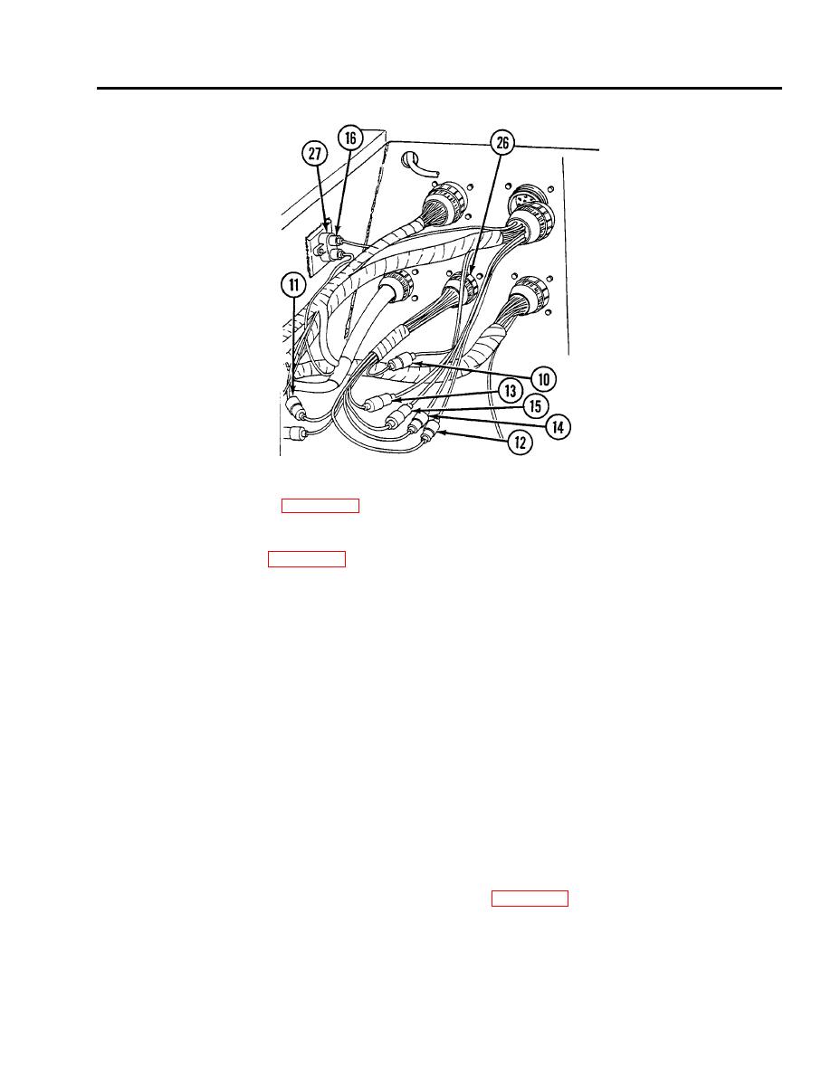
Disconnect connector (16) from circuit breaker (27).
Disassembly
1.
Disassemble wiring harness (see WP 0255 00 thru 0264 00, as appropriate).
Assembly
1.
Assemble wiring harness (see WP 0255 00 thru 0264 00, as appropriate).
Installation
1.
Connect connector (16) to circuit breaker (27).
2.
Connect seven connectors (9 through 15) to bulkhead to main engine wiring harness and starter relay wiring harness (26).
3.
Connect connector (8) to main engine disconnect (25).
4.
Connect three connectors (5, 6, and 7) to batteries to master relay, voltage regulator, slave receptacle, and engine disconnect
wiring harness (24).
5.
Connect connector (4) to switching relay box (23).
6.
Connect connector (3) to APU and main engine armature relays to voltage regulator wiring harness (22).
7.
Connect connector (2) to rear fuel tank transmitter (21).
8.
Connect connector (1) to bulkhead disconnect (20).
9.
Install 16 clamps (17) using lockwasher (19) and screw (18) for each.
NOTE
Follow-on maintenance: Install air inlet doors if removed (see WP 0341 00).
END OF WORK PACKAGE
0223 00-5/6 blank


