TM 9-2350-256-20-2
0402 00
Adjustment
1.
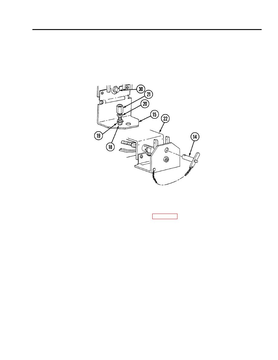
Loosen two nuts (19 and 20) and back off screw (18) and stop (21).
2.
Close shield (15) and insert quick-release pin (14) through shield and bracket (22) to locked position.
3.
Push in button on manual control lever (30) and adjust screw (18) until it touches switch button. Back off screw 1/2 turn.
Tighten nut (19) to lock screw.
4.
Turn stop (21) in until it seats firmly against rim of manual control lever (30). Turn nut (20) in until it seats firmly against
stop. Remove quick-release pin (14) and open shield (15). Tighten nut without allowing stop to rotate.
5.
Repeat step 2 and check for switch operation and locked position of pin.
NOTE
Follow-on maintenance: Install heater control box (see WP 0161 00).
END OF WORK PACKAGE
0402 00-11/12 blank


