TM 9-2350-256-20-2
0467 00
d.
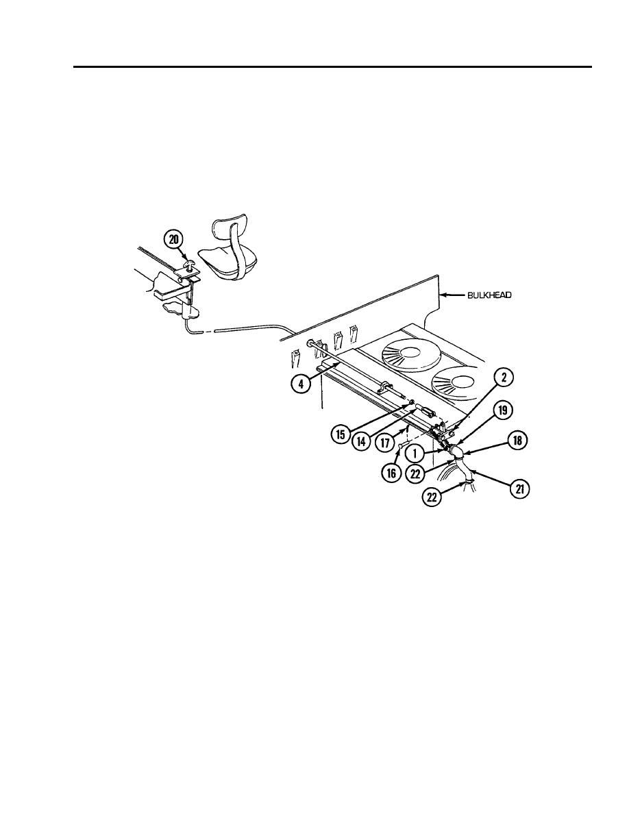
Install clevis (14) and nut (15) onto end of control cable (4). Tighten nut.
e.
Attach clevis (14) to valve assembly (1) with pin (16) and cotter pin (17).
9.
Position air exhaust elbow (18) on shroud connection in an inverted position (pointing up) and secure with hose clamp (19).
10. Operate hand lever by exerting sufficient pull on T-handle (20) and valve assembly (1), and lock in place by rotating
T-handle clockwise.
11. Fill air exhaust elbow (18) with water and allow to sit for 5 minutes. If valve assembly (1) is seated properly and no leakage
is detected, reposition valve assembly by loosening two screws (2). Then, tighten screws and recheck for watertight seal.
12. Reposition air exhaust elbow (18) on exhaust air tubes (21) and shroud connection and secure with two hose clamps (22).
END OF WORK PACKAGE
0467 00-3/4 blank


