SECTION I: MAIN WINCH ASSEMBLY
TM 9-2350-256-20
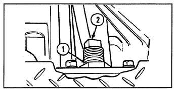
ADJUSTMENT
1
Loosen locknut (1).
2
Tighten adjusting screw (2) clockwise to maximum.
Back off adjusting screw 1 full turn. Hold
adjusting screw in position and tighten locknut (1).
NOTE
Follow-on maintenance:
Install right front
access floor plate (see
paragraph 9-2)
11-3 REPLACE MAIN WINCH MANUAL CONTROL AND LINKAGE
THIS TASK COVERS
a. Removal
b. Installation
INITIAL SET-UP
Tools:
Parts:
Tool kit, general mechanic's (Appendix C, item 53)
Drivescrews (4) (Appendix G, item 13)
Lockwashers (2) (Appendix G, item 132)
Pins, cotter (2) (Appendix G, item 212)
Pin, cotter (Appendix G, item 214)
a. REMOVAL
1
Disconnect winch shift rod (1) from winch shift
lever (2) by removing two cotter pins (3) and
straight pin (4).
2
Remove knob (5) from winch shift lever (2).
3
Remove winch shift lever (2) from bracket (6) by
removing cotter pin (7), screw (8), and nut (9).
4
Remove bracket (6) by removing two screws (10)
and two lockwashers (11).
5
Remove main winch identification (ID) plate (12)
by removing four drivescrews (13).
b. INSTALLATION
1
Install main winch ID plate (12) with four new
drivescrews (13).
2
Install bracket (6) with two new lockwashers (11)
and two screws (10).
3
Install winch shift lever (2) to bracket (6) with
screw (8), nut (9), and new cotter pin (7).
4
Install knob (5) onto winch shift lever (2).
5
Connect winch shift rod (1) to winch shift lever (2)
with straight pin (4) and two new cotter pins (3).
11-3