SECTION V: TROUBLESHOOTING
TM 9-2350-256-20
WARNING
Remove all jewelry such as rings, dog tags,
bracelets, etc. If jewelry contacts a metal
surface a direct short may result in instant
heating of tools, damage to equipment, and
injury or death to personnel.
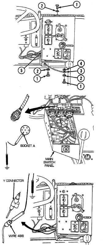
A Remove three screws (1), three lockwashers (2), ground
lead (3), flat washer (4), and release main switch panel
(5) from mounting brackets. Disconnect switch panel to
neutral safety to bulkhead wiring harness from main
switch panel. Place red lead of multimeter in socket A of
wire 14 and black lead to ground. Turn MASTER switch
on, push START switch, and check for voltage. Turn
MASTER switch OFF. If voltage is not present, go to
step 0. If voltage is present, go to step B.
B Reconnect switch panel to neutral safety to bulkhead
wiring harness to main switch panel. Install main switch
panel (5), flat washer (4), ground lead (3), three
lockwashers (2), and three screws (1) to mounting
bracket. Disconnect wire 486 at Y-connector rear main
switch panel on manifold preheat switch side. Place red
lead of multimeter on male connector of wire 486 and
black lead to ground. Turn MASTER switch on, push
START switch, and check for voltage. Turn MASTER
switch OFF. If voltage is present, go to step C. If
voltage is not present, repair/replace wire 14 of switch
panel to neutral safety to bulkhead wiring harness (see
paragraph 6-54).
2-73