SECTION V: TROUBLESHOOTING
TM 9-2350-256-20
WARNING
Remove all jewelry such as rings, dog tags,
bracelets, etc. If jewelry contacts a metal
surface a direct short may result in instant
heating of tools, damage to equipment, and
injury or death to personnel.
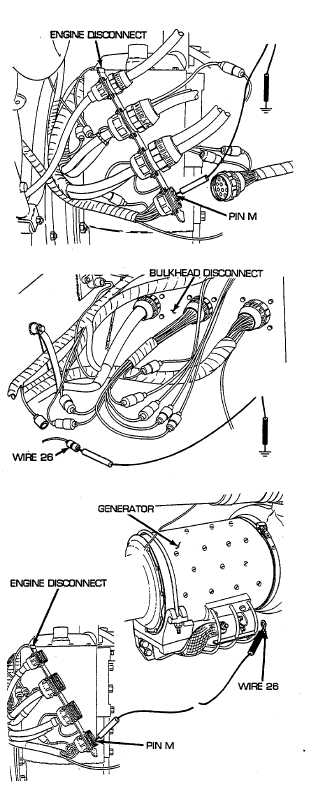
D Reconnect APU control box to foot dimmer switch
and bulkhead wiring harness to bulkhead. Remove
engine deck (see paragraph 9-51). Disconnect
bulkhead to engine bracket and rear fuel tank
transmitter wiring harness from engine disconnect.
Place red lead of multimeter on pin M of wire 26 and
black lead to ground. Turn MASTER switch on, start
engine, set to idle, and check for voltage. Turn
engine and MASTER switch OFF. If voltage is
present, go to step E. If voltage is not present, go to
step F.
E Reconnect bulkhead to engine bracket and rear fuel
tank transmitter wiring harness to engine
disconnect. Disconnect wire 26 of bulkhead to APU,
master relay, and rigger's lights wiring harness
from bulkhead to engine bracket and rear fuel tank
transmitter wiring harness. Place red lead of
multimeter in female connector of wire 26 and black
lead to ground. Turn MASTER switch on, start
engine, set to idle, and check for voltage. Turn
engine and MASTER switch OFF. If voltage is
present, repair/replace wire 26 of bulkhead to
APU, master relay, and rigger's lights wiring
harness (see paragraph 6-75 for dual voltage; 6-76
for single voltage). If voltage is not present,
repair/replace wire 26 of bulkhead to engine
bracket and rear fuel tank transmitter wiring
harness (see paragraph 6-73 for dual voltage; 6-74
for single voltage).
F Remove powerplant (see paragraph 3-1). Place red
lead of multimeter on pin M of wire 26 and black
lead of multimeter on wire 26. Check for continuity.
If continuity is present, replace generator (see
paragraph 6-1). If continuity is not present,
repair/replace wire 26 of engine wiring harness (see
paragraph 6-58 for dual voltage; 6-59 for single
voltage).
2-215