CHAPTER 6: MAINTENANCE OF ELECTRICAL SYSTEMS AND CIRCUITS
TM 9-2350-256-20
6-10 REPLACE/REPAIR MAIN SWITCH PANEL ASSEMBLY-Continued
18 Remove three connectors (50) by removing four
screws (51) and four nuts (52) from each.
19 Remove panel (53) by removing two screws (54).
20 Disassemble wiring harnesses and lead assembly
(see Chapter 6, Section VII).
c. ASSEMBLY
1
Assemble wiring harnesses and lead assembly (see
Chapter 6, Section VII).
2
Install panel (53) using two screws (54).
3
Install three connectors (50) using four screws (51)
and four nuts (52) for each.
4
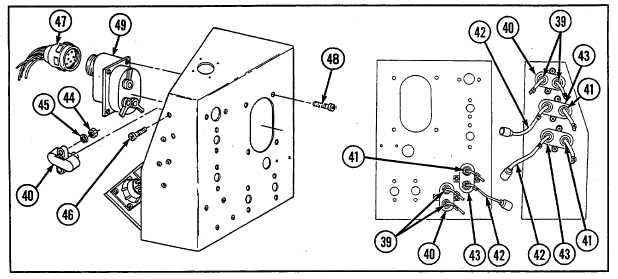
Install switch (49) using four screws (48), and connect connector (47).
5
Install five circuit breakers (40 and 43) using two screws (46), two new lockwashers (45), and two nuts (44) for
each.
6
Install lead assembly (42) to three circuit breakers (43), and connect connector (41).
7
Connect two connectors (39) to two circuit breakers (40).
8
Install switch guard (36), pull switch (37), nut (35), and connect connector (38).
9
Connect two connectors (34) to switch (32).
10 Install switch (32), ID plate (31), and switch guard (30) using two screws (33).
6-34