SECTION V: VEHICLE WIRING
TM 9-2350-256-20
1 Connect connector (11) to B.O. selector lead assembly (19).
2 Connect connector (10) to main lighting and B.O. selector switch wiring harness (13).
3 Connect connector (9) to master relay switch (17).
4 Connect connector (8) to master relay indicator lamp assembly (18).
5 Connect connector (7) to master relay switch (17).
6 Install connector (6) using four screws (15) and four nuts (16).
7 Connect four connectors (2 through 5) to main lighting and B.O. selector switch wiring harness (13).
8 Connect connector (1) to main lighting switch (12).
NOTE
Follow-on maintenance: Install main switch panel (see paragraph 6-10)
6-71 REPLACE/REPAIR BULKHEAD TO MASTER RELAY AND LEFT AND RIGHT
TAILLIGHT WIRING HARNESS (116718131
THIS TASK COVERS
a. Removal
b. Disassembly
c. Assembly
d. Installation
INITIAL SET-UP
Tools:
Parts:
Equipment Condition:
Tool kit, general mechanic's
Lockwashers (11) (Appendix G,
Engine deck removed (see
(Appendix C, item 53)
item 116) paragraph 9-51)
WARNING
Be certain MASTER switch is OFF when working on electrical systems to avoid electrical shock and bums.
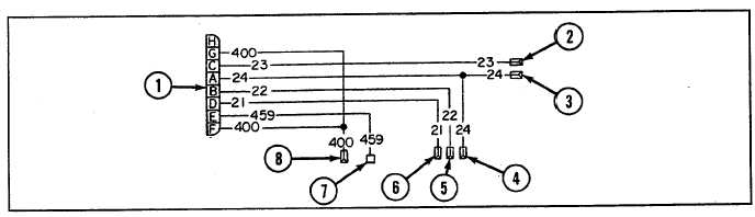
Connector No.
Electrical Lead To:
Wire No.
1
Bulkhead disconnect
400, 23, 24, 22, 21, 459, 400
2
Right hand taillight
23
3
Right hand taillight
24
4
Left hand taillight
24
5
Left hand taillight
22
6
Left hand taillight
21
7
Master relay
459
8
Circuit breaker
400
6-181