SECTION V: VEHICLE WIRING
TM 9-2350-256-20
3 Connect connector (9) to bilge pump indicator light (22).
4 Connect connector (8) to circuit breaker no. 3 (21).
5 Connect connector (7) to circuit breaker no. 2 (19).
6 Connect two connectors (5 and 6) to winch light switch (20).
7 Connect connector (4) to circuit breaker no. 2 (19).
8 Connect connector (3) to circuit breaker no. 1 (18).
9 Connect connector (2) to vent blower switch (17).
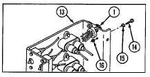
10 Install connector (1) to electrical accessories panel
outlet (13) using four screws (14), four new
lockwashers (15), and four nuts (16).
NOTE
Follow-on maintenance: Install electrical
accessories panel (see
paragraph 6-9)
6-85 REPLACE/REPAIR BILGE PUMP CIRCUIT BREAKER TO SWITCH PANEL
LEAD (10894546)
THIS TASK COVERS
a. Removal
b. Disassembly
c. Assembly
d. Installation
INITIAL SET-UP
Tools:
Equipment Condition:
Tool kit, general mechanic's (Appendix C, item 53) Stowage basket forward intermediate left floor
plate opened (paragraph 9-21)
Parts:
Lockwasher (Appendix G, item 115)
WARNING
Be certain MASTER switch is OFF when working on electrical systems to avoid electrical shock and burns.
Connector No.
Electrical Lead To:
Wire No.
1
Bilge pump circuit breaker
450A
2
Switch panel, radio, and bilge pump to bulkhead wiring
450A
harness
6-229


