CHAPTER 6: MAINTENANCE OF ELECTRICAL SYSTEMS AND CIRCUITS
TM 9-2350-256-20
6-114 REPAIR TYPICAL FEMALE-TYPE PLUG
THIS TASK COVERS
a. Disassembly
b. Assembly
INITIAL SET-UP
Tools:
Reference:
Tool kit, general mechanic's (Appendix C, item 53)
TB SIG 222
WARNING
Be certain MASTER switch is OFF when working on electrical system to avoid electrical shock and bums.
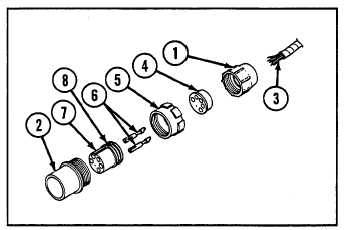
a. DISASSEMBLY
1
Unscrew nut (1) from shell assembly (2) and slide back
on cable leads (3).
2
Slide grommet (4) back on cable leads (3).
3
Slide coupling nut (5) off shell (2).
4
Drive socket contacts (6) out through rear if insert (7)
with pin extractor.
5.
Push insert (7) out through rear shell (2).
6.
Unsolder cable leads (3) from socket contacts (5).
b. ASSEMBLY
1
Strip cable leads (3) insulation equal to depth of solder wells of socket contacts (6).
2
Slide nut (1) over cable leads(3).
3
Slide grommet (4) over cable leads (3).
4
Insert cable leads (3) into solder wells of socket contacts (6) and solder (use resin core solder only) (refer to TB SIG
222).
5
Push insert (7) into shell (2) from rear until seated. Groove (8) in insert must be aligned with guide in shell (2) to
ensure proper fit.
6
Push socket contacts (6) into insert (7) from rear until seated.
7
Slide coupling nut (5) onto shell assembly (2).
8
Push grommet (4) down cable leads (3) and over solder wells of sockets contacts (6).
9
Screw nut (1) onto shell assembly (2).
6-270