SECTlON II:
TRANSMlSSlON OIL COOLER LINES, BRACKET. SADDLE
SEALS, AND OUTPUT REDUCTION DRIVES
TM 9-2350-256-20
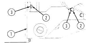
a. REMOVAL
Remove transmission roller bracket assembly (1) from
transmission by removing five screws (3) and five
lockwashers (3).
b. INSTALLATION
Install transmission roller bracket assembly (1) on
transmission with five screws (2) and five new
lockwashers (3).
NOTE
Follow-on maintenance:
Install powerplant (see paragraph 3-1)
7-4
REPLACE TRANSMISSION TORQUE CONVERTER DRAIN PLUGS
THIS TASK COVERS
a. Removal
b. Installation
INITIAL SET-UP
Tool:
Reference:
• Tool kit, general mechanic’s (Appendix C, item 53)
TM 9-2350-256-10
• Key, socket head screw (Appendix C, item 24)
Parts:
•Gasket (Appendix G, item 56)
•Gasket (Appendix G, item 61)
•Gasket (Appendix G, item 65)
Equipment Condition:
Engine deck removed (see paragraph 9-51)
•Lockwashers (18) (Appendix G, item 138)
a. REMOVAL
1
Remove six bolts (1), six lockwashers (2), drain cover (3), and gasket (4) from dram access
2
Place suitable container under torque converter
3
Remove four drain plugs (5).
4
Remove five plugs (6 and 7), if necessary.
Change 1
7-5