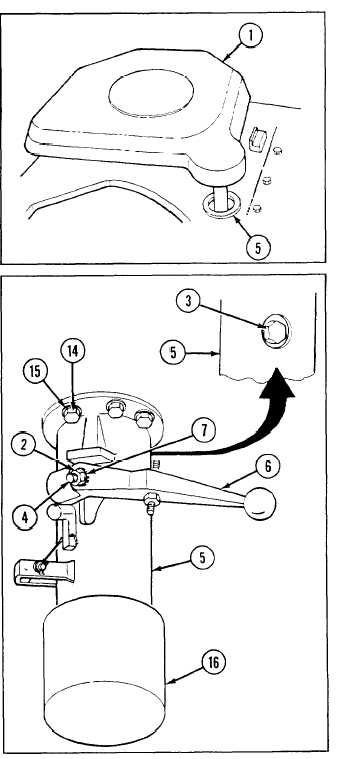
3
Remove rigger’s cab-top door (1) by pulling up
through shaft housing (5).
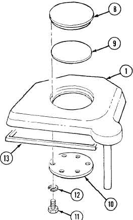
4
Remove access cover (8), gasket (9), and access
cover (10) from inside rigger’s cab-top door (1) by
removing six screws (11) and six lockwashers (12).
5
Remove rubber strip (13) from rigger’s cab-top
door (1).
6
Remove shaft housing (5) by removing five screws
(14) and five lockwashers (15).
7
Remove cushioning pad (16) from shaft housing
(5).
SECTION II: HULL AND CAB COMPONENTS
TM 9-2350-256-20
a. REMOVAL
1
Raise rigger’s cab-top door (1) about 2 in. (51 mm) to aline self-locking nuts (2 and 3) on arm control pin (4)
with opening in shaft housing (5).
2
Remove control arm (6) by removing self-locking nut (2), arm control pin (4), washer (7), and self-locking nut
(3).
9-51