SECTION II: HULL AND CAB COMPONENTS
TM 9-2350-256-20
6
8
9
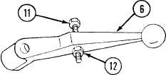
Remove adjusting screw (11) and self-locking nut
(12) from control arm (6).
7
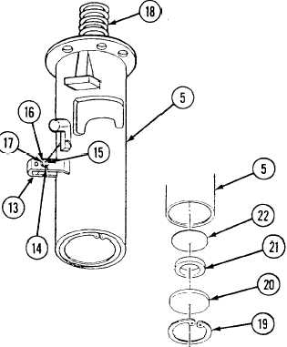
Remove retaining latch (13) by removing cotter pin
(14), straight pin (15), spring (16), and washer (17).
Remove spring (18) from shaft housing (5).
Remove retaining ring (19), bearing retainer (20),
bearing (21), and disk (22).
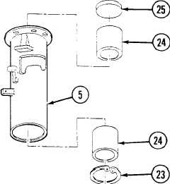
b. DISASSEMBLY
Remove retaining ring (23), two bearings (24), and
packing (25) from shaft housing (5).
c. ASSEMBLY
Install two bearings (24), retaining ring (23), and new
packing (25) in shaft housing (5) and lubricate (see
Appendix J).
d. INSTALLATION
1
Install disk (22), bearing (21), and bearing retainer
(20), and secure with retaining ring (19).
2
Install spring (18) in shaft housing (5).
3
Install retaining latch (13) with straight pin (15),
spring (16), washer (17), and new cotter pin (14).
4
Install adjusting screw
(12) on control arm (6).
(11) and new self-locking nut
Change 1
9 - 4 9