SECTION II: HULL AND CAB COMPONENTS
TM 9-2350-256-20
d.
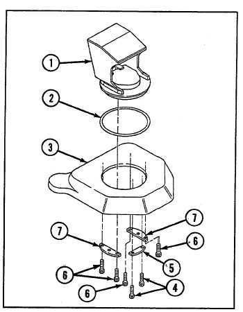
INSTALLATION
Install mount assembly (1) on driver's cab-top door (3) with
new gasket (2), two new self-locking screws (4), plate (5),
four screws (6), and two plates (7).
9-39 REPLACE INFRARED POWER SUPPLY
THIS TASK COVERS
a.
Removal
b. Installation
INITIAL SET-UP
Tools:
Parts:
Tool kit, general mechanic's (Appendix C, item 53)
Lockwashers (4) (Appendix G, item 117)
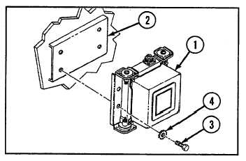
a.
REMOVAL
Remove power supply (1) from mount (2) by removing four
screws (3) and four lockwashers (4).
b.
INSTALLATION
Install power supply (1) on mount (2) with four new
lockwashers (4) and four screws (3).
9-65