TM 9-2350-256-34-1
2 - 4 3 . H y d r a u l i c O i l T a n k C o v e r A s s e m -
b l i e s a n d S u c t i o n P i p e
a. Hydraulic Oil Tank Top Couer Assemblies.
(1) Removal. Prior to removing the oil tank front
and rear top cover assemblies, remove subfloor plates
9, 10, 11 (fig. 2-3), disconnect five hydraulic lines
(View C, fig. 2-39) and remove fittings (TM 9-2350-
256-20). Remove the oil tank top cover assemblies as
shown in figure 2-42.
(2) Installation. Install the hydraulic oil tank
front and rear top cover assemblies in reverse order of
removal.
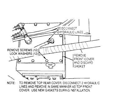
b. Hydraulic Oil Tank Front Cover Assembly.
(1) Removal. Prior to removing the oil tank front
cover assembly, remove subfloor plate 11 (fig. 2-3),
dram the tank below the level of the cover, disconnect
hydraulic lines (View A, fig. 2-39) and remove fittings
(TM 9-2350-256-20). Remove the oil tank front cover
assembly in the same manner as the top cover assem-
blies (fig. 2-42).
(2) lnstallation. Install the oil tank front cover as-
sembly in reverse order of removal and fill tank (TM
9-2350-256-20).
Figure 2-42. Hydraulic oil tank top covers - removal and installation.
c. Hydraulic 0i1 Tank Suction Pipe.
(1) Removal. The suction pipe is located inside the
oil tank directly behind the oil filter. Prior to removing
the suction pipe, drain the oil tank below the level of
the filter and remove the top rear tank cover (a above).
Remove four screws and lock washers and the two split
flanges holding the suction pipe. Remove the suction
pipe and packing.
(2) Installation. Install the suction pipe and pack-
ing in reverse order of removal and refill the tank (TM
9-350-256-20).
2 - 4 4 . F o r w a r d F u e l T a n k A s s e m b l y
NOTE
The tank may be stripped of all fittings, fuel
- pump and sending unit, while installed, for
ventilation purposes (TM 9-2350-256-20).
a. Prior Operations. Prior to removal of the forward
fuel tank, perform the following operations:
(1) Remove commander’s and rigger’s seats, hoist
winch cable chute and the drain valve controls and
control lever bracket (TM 9-2350-256-20). Remove
subfloor plates 3. 5, 9, 10, 11, 12. 13, 14, 17, 18, 20.
21, 22 and 24 (fig. 2-3).
(2) Remove main winch and spade assembly (para
2-25) and hoist winch assembly (para 2-35). Remove
mechanical transmission and hydraulic pump assem-
bly (para 2-32) and hydraulic system oil tank assembly
(para 2-40).
(3) Disconnect mechanical transmission power
takeoff drive shaft at main engine and remove shaft
entirely (fig. 2-30).
(4) Remove auxiliary power unit control box and
bracket and the shift and throttle control components
mounted on floor plates (TM 9-2350-256-20). Re-
move any stowage racks and boxes interfering with re-
moval of the tank (TM 9-2350-256-20).
(5) Support rear (lower) end of hydraulic control
panel (subplate) by opening operator’s and mechanic’s
hatches and looping a chain through the hatches.
Secure the chain to lower end of panel to support it.
Remove attaching bolts at rear support bracket and re-
move subfloor plate 1 (fig. 2-3).
b. Remoual. Remove the forward fuel tank assembly
as shown in figure 2-43.
2-74
Change 8