TM 9-2350-256-34-1
Section X. REPAIR OF FIRE EXTINGUISHER
STOWAGE BOXES AND BRACKETS
3-81.
Description
The fire extinguisher system is comprised of eight 10-
pound cylinders, cylinder control valve, remote control
connectors, two dual-pull mechanisms, extinguisher
lines, seven nozzles with cables, and two interior remote
control pull handles with cables, and an engine shutoff
switch. The cylinders are mounted in banks of four on
each side of the cab interior.
3-82.
Removal and Installation
Refer to TM 9-2350-256-20 for removal and installation
of fire extinguisher stowage boxes and brackets.
3-83.
Disassembly
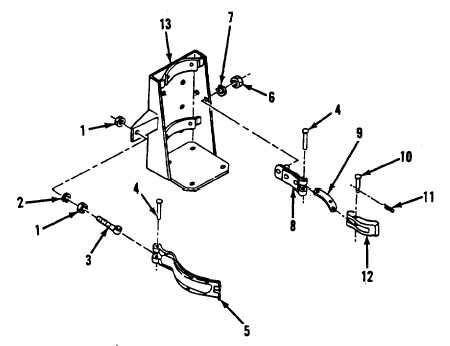
Refer to figure 3-28 for disassembly of fire extinguisher
stowage box.
3-84.
Assembly
Assemble the fire extinguisher stowage box in reverse
order of disassembly.
Legend for figure 3-28:
1
Nut (2)
2
Lockwasher
3
Rod connector
4
Rivet (2)
5
Fixed Arm Assembly
6
Nut
7
Lockwasher
8
Retaining trap
9
Connecting link
10
Straight pin
11
Cotter pin
12
Rod end clevis
13
Mounting bracket
Figure 3-28. Fire extinguisher stowage boxes-disassembly and assembly
3-50 CHANGE 7