TM 9-2350-256-34-1
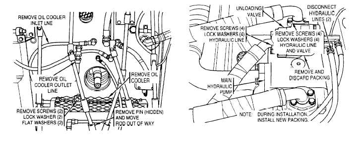
Figure 2-32. Mechanical transmission oil cooler assembly
and lines-removal and installation.
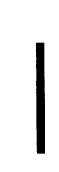
Figure 2-33. Main hydraulic pump unloading valve -
removal and installation.
N O T E
b . I n s t a l l a t i o n . I n s t a l l t h e m e c h a n i c a l t r a n
smission oil cooler assembly and lines in reverse or-
der of removal.
2-34. Main Hydraulic Pump Unloading Valve
P r i o r t o r e m o v i n g t h e m a i n h y d r a u l i c p u m p
unloading valve, remove subfloor plates 11, 12 and
14 (fig. 2-3) Remove and install the main hydraulic
pump unloading valve as shown in figure 2-33.
I f y o u r v e h i c l e h a s h o i s t w i n c h
a s s e m b l y 8 7 3 9 0 0 9 - 1 1 o r 8 7 3 9 0 0 9 - 1 ,
s e n d
w i n c h
a s s e m b l y
t o d e p o t
m a i n t e n a n c e f o r r e m o v a l o f a n t i -
c h a t t e r k i t .
2-35. Hoist Winch Assembly
a. Removal. Prior to removing the hoist winch
assembly, remove the hoist winch cable (para 2-231.
Remove the cupola and cupola plate. commander’s
s e a t
a n d h o i s t w i n c h c a b l e c h u t e ( T M
9-2350-256-20,. Remove any oddment trays. racks
and baskets, as required. to allow clearance and
prevent damage. Remove subfloor plates 4, 5, 11,
17, 18, 19, 20, 21. and 24 (fig. 2-3). Remove hoist
winch assembly as shown in figure 2-34.
Change 8
2-65