TM 9-2350-256-34-2
c. Main Winch Combination Control Valve Adjustment. Adjust to achieve winching requirements as follows:
CAUTION
Do not exceed 1900 psi relief pressure.
Step 1 If using load cell, adjust relief pressure to achieve desired pull by turning adjusting screw on main winch
combination control valve (figure 2-4). Turning in clockwise direction will increase pressure.
88,000 - 92,000 lb pull with cable off nose roller
83.000 - 87,000 lb pull with cable over nose roller
Step 2 If using load cell, activate winch to INHAUL in low gear. If using anchor, activate winch to INHAUL. If using
winch brake, activate winch to pay out.
Step 3 If using anchor or winch brake, adjust relief pressure to original value recorded in Vehicle Log Book.
Step 4 Verify setting with locking nut in locked position, and record new setting in Vehicle Log Book.
Step 5 Disconnect pressure gage. Disconnect load cell or anchor, or readjust winch brake as necessary.
Step 6 Verify pay out and inhaul.
NOTE
If adjustment was done using load cell, no further load test is required. If adjustment
was done using anchor or brakes. Proceed with load test below.
d. Load Test.
Step 1 Verify winching capability by attaching winch cable to a vehicle with the towed vehicle transmission in neutral.
Step 2 Winch vehicle at least 10 feet.
Step 3 If vehicle fails to pass the load test, perform adjustment procedures as presented in paragraph 2.20 b thru d.
2-21. Adjustment and Load Test of Hoist Winch
NOTE
Valves are adjusted by vehicle manufacturer. Should verification or adjustment be
required, these procedures shall be used.
a. General. The hoist winch shall have a vertical lifting capacity of 30,000 pounds, full drum and 50,000 pounds bare
drum, using a four-part line (3 to 5 wraps minimum of cable on a bare drum). The hoist winch combination control valve
shall be adjusted by the followingprocedures so that the hoist will have the lifting capacity as specified.
NOTE
For bare drum verification of hoist winch combination control valve, a test cable may
be fabricated not to exceed 110 ft in length, using fabrication instructions in
paragraph 3-8e.
b. Vehicle preparation. Prior to adjusting hoist winch combination control valve, the following shall be accomplished:
WARNING
Test components (pressure gages, hoses, and fittings) must be capable of
withstanding a working pressure of 1950 to 2050 psi.
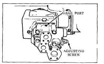
Step 1 Install pressure gage (NSN 4810-00-766-3355) in hoist winch combination control valve gage port (figure 2-5).
Figure 2-5. Hoist winch combination control valve gage port and adjusting screw.
Change 5
2-29


