TM 9-2350-256-34-2
2-22. Adjustment and Load Test of Live Boom Capability.
a. Vehicle preparation. Prior to adjusting boom combination control valve (figure 2-7) the following shall be
accomplished:
WARNING
Test components (pressure gages, hoses, and fittings) must be capable of
withstanding a working pressure of 1950 to 2050 psi.
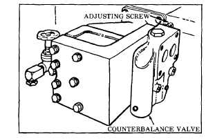
Figure 2-6. Counterbalance valve adjusting screw.
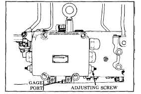
Step 1 Install pressure gage (NSN 4910-00-766-3355) in boom combination control valve rear gage port (toward rear of
vehicle). Refer to figure 2-7 for location of test gage port.
Figure 2-7. Boom combination control valve gage port and adjusting screw.
Step 2 If using load cell or calibrated weights, rig a four-part line and extend the boom to an 8-foot reach. Attach load
cell or weights. Load cell must be anchored. If a load cell or weights are not available, place boom in STOW
position. Then block boom in a partially raised position using 2 x 4 wooden blocks on top of each armor air
intake cover. (Covers are located at the top rear of the crew compartment.)
Step 3 Set engine speed at 1600-1800 rpm.
NOTE
The adjustment and load test shall be accomplished with the hydraulic reservoir oil
temperature at 1000F to 1300F.
b. Boom combination control valve adjustment. (figure 2-7) Adjust to achieve live boom capability as follows:
CAUTION
Do not exceed 1700 psi relief pressure.
Step 1 If using load cell or weights, activate boom valve to RETRACT position and use adjusting screw on boom
combination control valve (figure 2-7) to achieve a pull of 50,000 to 55,000 pounds. Turning in a clockwise
direction will increase pressure. If blocking the boom, place the boom operating lever in RETRACT position and
boom safety control lever in STOW position. Adjust boom combination control valve rear relief (toward rear of
vehicle) to 1600 psi by turning the adjusting screw (figure 2-7). Turning in clockwise direction will increase
pressure.
NOTE
Pressure should be between 1550 and 1650 psi. Do not exceed 1650 psi.
Step 2 Verify pressure with locking nut set in locked position and record new setting in Vehicle Log Book.
TA171826
Change 4
2-31


