TM 9-2350-256-34
0035 00
Removal
1.
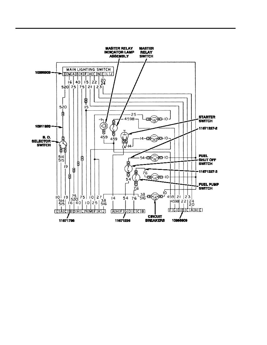
The main switch panel wiring diagram is provided below:
2.
Remove three leads (no. 520 connecting no. 520 from light switch panel connector to blackout selector, no. 54 from fuel
shutoff switch to circuit breaker, and no. 76 from fuel pump switch to circuit breaker).
3.
Disconnect two leads (1) and eight leads (2).
4.
Disconnect main lighting switch and master relay wiring harness (3) from main lighting switch (4).
5.
Disconnect 5 leads (5) and 13 leads (6).
6.
Remove 12 self-locking nuts (7), screws (8), and 3 wiring harnesses (3, 9, and 10). Discard self-locking nuts.
7.
Remove lead (11).
0035 00-2


