TM 9-2350-256-34
0053 00
Removal
1.
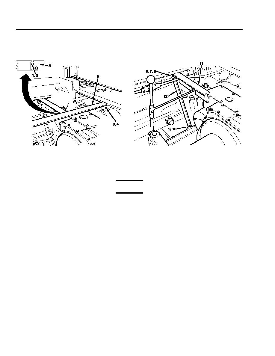
Remove two screws (1), lockwashers (2), four screws (3), lockwashers (4), and cross support (5). Discard lockwashers.
2.
Remove two nuts (6), lockwashers (7), bolts (8), screws (9), lockwashers (10), support bar (11), and support bar brace (12).
Discard lockwashers.
Remove clamp and fire extinguisher tube (13) in accordance with TM 9-2350-256-20.
3.
Remove cotter pin (14), pin (15), self-locking nut (16), bolt (17), and shift rod (18) and lever (19) together as a unit. Discard
4.
cotter pin and self-locking nut.
WARNING
Keep drain valve (20) closed.
5.
Disconnect drain line (21) from drain valve (20).
6.
Disconnect hydraulic line (22) from motor (23).
7.
Disconnect four hydraulic lines (24) from combination control valve (25).
NOTE
The flange-type hydraulic hoses (29), attaching hardware (26, 27, and 28), and packings (30) are hidden
between combination control valve (25) and vehicle wall.
8.
Remove eight screws (26), lockwashers (27), four flanges (28), and disconnect two flange-type hydraulic hoses (29).
Discard lockwashers.
0053 00-2


