
TM 9-2350-256-34
0053 00
NOTE
There are two methods of removing the hoist winch assembly (38) from this point: steps 14 thru 17 or
steps 18 thru 23.
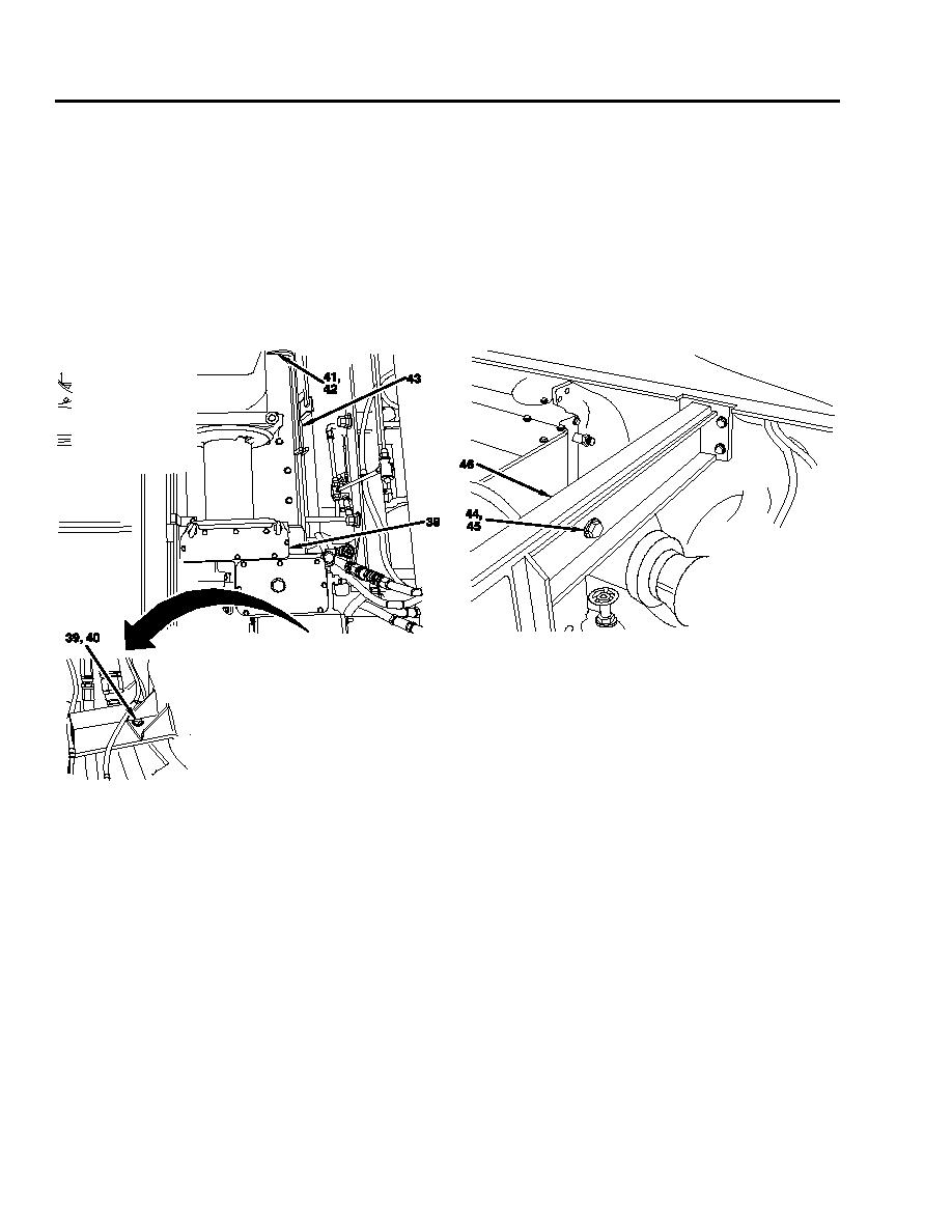
14. Using sling, support weight of hoist winch assembly (38) and remove two screws (39), lockwashers (40), screws (hidden)
(41), lockwashers (hidden) (42), and let front support (43) down for clearance. Discard lockwashers.
15. Continue to support weight of hoist winch assembly (38) with sling and remove two screws (44) and lockwashers (45) from
cross support beam (46). Discard lockwashers.
16. Move hoist winch assembly (38) forward to clear cross support beam (46) and raise hoist winch assembly.
17. Remove hoist winch assembly (38) thru cupola plate opening.
NOTE
Steps 18 thru 23 is the alternate method of removing the hoist winch assembly (38).
18. Using sling, support weight of hoist winch assembly (38) and remove two screws (44) and lockwashers (45) from cross
support beam (46). Discard lockwashers.
19. Remove two screws securing mechanical transmission and main hydraulic pump assembly to cross support beam (46).
20. Raise and block mechanical transmission and main hydraulic pump assembly to clear cross support beam (46).
21. Mark shims (47) and cross support beam (46) so they may be installed in the same place from which they were removed
to prevent misalignment of winch and mechanical transmission mounting holes. Remove eight screws (48), lockwashers
(49), and shims. Discard lockwashers.
22.
Tip cross support beam (46) to clear from under mechanical transmission support and lift cross support beam out of way.
0053 00-4
