TM 9--2350--292--20--1
0205 00--3
FUEL INJECTOR NOZZLE RETURN HOSES AND RELATED PARTS
REPLACEMENT -- CONTINUED
0205 00
Installation
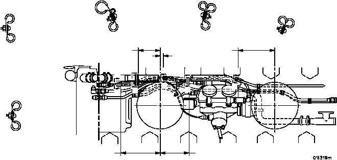
1. Install hose assemblies, tube assemblies and fittings in accordance with the following legend and illustrations.
2. Secure hose assemblies, tube assemblies and fittings with clamps, attaching hardware and new self--locking nut,
new lockwashers and new copper flat washers as shown in legend and illustrations.
9.00 IN
(229 MM)
.75 IN
(19.05 MM)
3.25 IN
(82.6 MM)
9.00 IN
(229 MM)
5.75 IN
(146.06MM)
7/16 (11.0MM)
11/16 (17.5MM)
7/16 (11.0MM)
11/16 (17.5MM)
1/2 (12.7MM)
1/2 (12.7MM)
1--1/4 (31.8MM)
7/16 (11.0MM)
1/2 (12.7MM)
A
A
B
B
C
C
D
D
E
E
VIEW A--A
VIEW B--B
VIEW C--C
VIEW D--D
VIEW E--E
9/16 (14.3MM)
9/16 (14.3MM)
3/16 (4.8MM)
3. Torque 12 screws (1) to 135 lb--in (15 NSm).
LEGEND:
1.
Screws (12)
11.
Hose assembly
21.
Nut
2.
Flat washers (24)
12.
Connectors (2)
22.
Bolt
3.
Hose assemblies (10)
13.
Swivel tee
23.
Nut
4.
Connectors (8)
14.
Screw
24.
Adapter
5.
Hose assembly (8)
15.
Lockwashers (2)
25.
Loop clamp
6.
Tee (2)
16.
Loop clamps (3)
26.
Locknut
7.
Hose assembly
17.
Bracket
27.
Lockwasher
8.
Cross tube
18.
Lockwasher
28.
Tube nipple
9.
Hose assembly
19.
Screw
29.
Access cover (WP 0233 00)
10.
Clamp
20.
Self--locking nut
30.
Hose assembly
NOTE
FOLLOW--ON MAINTENANCE:
Install engine top housing assembly (WP 0232 00)
Install engine oil hose assemblies, tube assemblies and
related parts (WP 0200 00)


