TM 9--2350--292--20--1
0242 00--12
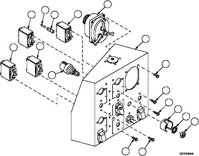
MAIN SWITCH PANEL ASSEMBLY REPAIR -- CONTINUED
0242 00
Assembly--Continued
7. Install shell (81) and plug (82) on blackout toggle switch (40) pin 1.
NOTE
The master and flasher switches are installed with lever
ON position up (pin 1 at the top); the fuel shutoff switch
with lever MOM ON position down (pin 1 at the bottom).
The blackout switch is installed with lever ON (A position)
up and lever ON (C position) down (pin 1 at the top and
pin 2 at the bottom). Perform step 8 to install each toggle
switch.
8. Install toggle switch (40, 47, 52, or 55) on main switch panel assembly (6) with two screws (80).
9. Install switch guard (79) and starter switch (51) on main switch panel assembly (6) with lockwasher (78) and nut
(77).
10. Install service lights switch (41) on main switch panel assembly (6) with four screws (76).
Figure 50
6
80
80
77
78
79
80
80
76
41
40
81
82
47
52
55
51