TM 9--2350--292--20--1
0291 00--5
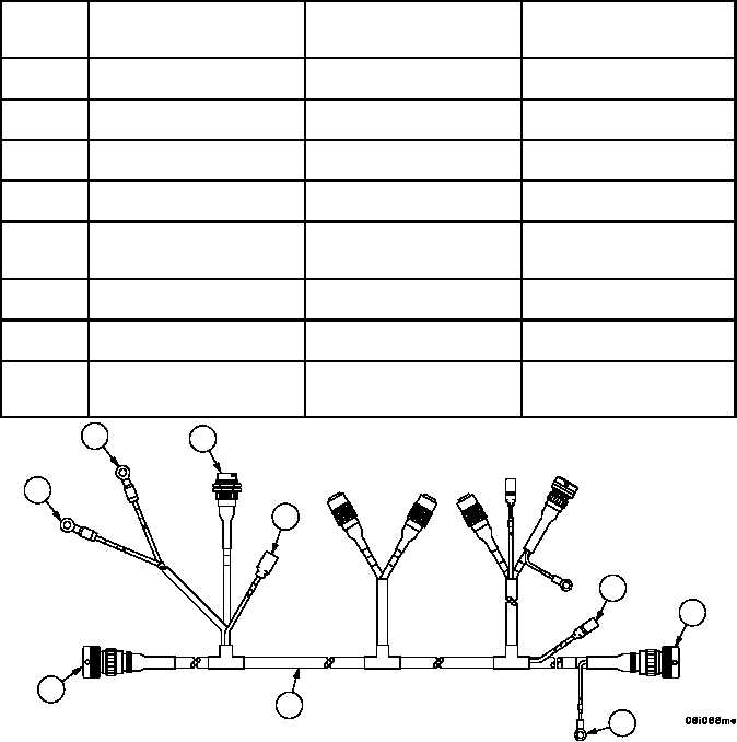
WIRING HARNESS 2W601 REPLACEMENT (OLD CONFIGURATION) --
CONTINUED
0291 00
Installation--Continued
NOTE
The following legend identifies attachment points for each
connection.
2. Install wiring harness (1) with attaching hardware, at the following attachment points:
Item
No.
2W601
Connector/Lead/Wire
To
Connector/Lead/Wire
Component
Location
15
Wire 591
Low Brake Pressure Warning
Switch
Crew Compartment
(Below Subfloor Plates)
14
Connector J1
Wiring Harness 2W602 Con-
nector P1
Crew Compartment
(Below Subfloor Plates)
13
Terminal 359B
Pay--Out Solenoid Valve
Crew Compartment
(Below Subfloor Plates)
12
Terminal 359B
Pay--In Solenoid Valve
Crew Compartment
(Below Subfloor Plates)
11
Connector P1
PTO/Accessory Panel
Crew Compartment
(Next to Hydraulic Control Pan-
el)
10
Terminal GND
Electromagnetic Clutch Power
Takeoff Ground
Crew Compartment
(Below Subfloor Plates)
9
Connector P2
Electromagnetic Clutch Power
Takeoff
Crew Compartment
(Below Subfloor Plates)
8
Wire 525
PTO High Temperature Switch
Electromagnetic Clutch Power
Takeoff (Below Subfloor
Plates)
Figure 103
8
9
10
15
11
12
13
14
1


