TM 9--2350--292--20--1
0070 00--3
ALL SIGNALS AT REMOTE TERMINAL UNIT CONNECTOR J5 ARE BELOW
VALID RANGE OR OPEN -- CONTINUED
0070 00
CONTINUED FROM STEP B
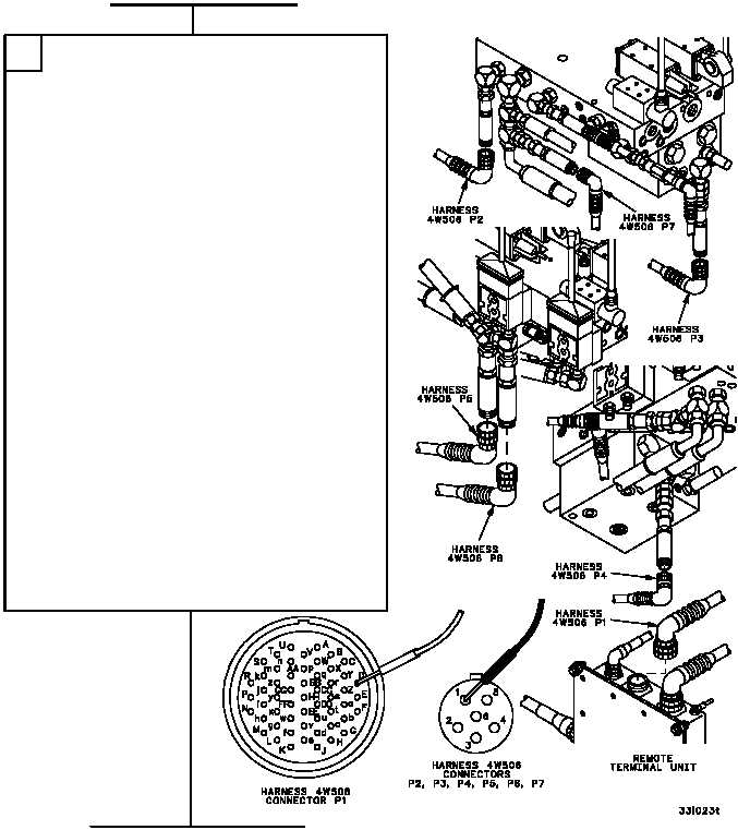
1. Disconnect wiring harness 4W506 from remote
terminal unit and sensors on the hydraulic
control valve manifold assembly (WP 0681 00).
2. Check wiring harness 4W506 using table
below. Place one multimeter lead on a pin in
the FROM column and the other lead on the
corresponding pin in the TO column. Check for
continuity.
FROM
TO
CONNECTOR/PIN
CONNECTOR/PIN
P1--D
P2--1
P1--E
P2--2
P1--F
P2--3
P1 Backshell
P2 Backshell
P1--G
P3--1
P1--H
P3--2
P1--J
P3--3
P1 Backshell
P3 Backshell
P1--K
P7--1
P1--L
P7--2
P1--M
P7--3
P1 Backshell
P7 Backshell
P1--P
P4--1
P1--R
P4--2
P1--S
P4--3
P1 Backshell
P4 Backshell
P1--T
P5--1
P1--U
P5--2
P1--V
P5--3
P1 Backshell
P5 Backshell
P1--W
P6--1
P1--X
P6--2
P1--Y
P6--3
P1 Backshell
P6 Backshell
C
CONTINUED ON NEXT PAGE