TM 9--2350--292--20--1
GAS PARTICULATE SYSTEM OVERVIEW AND DIAGRAMS
0077 00
THIS WORK PACKAGE COVERS:
Gas Particulate System Overview And Diagrams
There are two M3A3 gas/particulate filters and three M3 heater units in the vehicle. Each gas/particulate filter unit
supplies filtered air to up to 4 persons in the crew compartment. The unit removes all known chemical agents, dust
and other particles from the air. Filtered air is supplied from a M2A2 air purifier through hoses to a M25A1 mask
worn at the crew member or passenger station. The M2A2 air purifier has an M13 particulate filter, an M12A1 gas
filter, and an M1A1 air purifier precleaner.
Each unit consists of identical circuits using a common circuit breaker and separate control units, an M2A2 air puri-
fier assembly containing the blower motor, and related electrical wiring. Operating voltage (+24 -- 28 V dc) for the
filter system is supplied from the master relay circuits through an 80--amp circuit breaker. When the MASTER
switch is ON, the air purifier operates when the AIR PURIFIER switch in the control unit is turned ON.
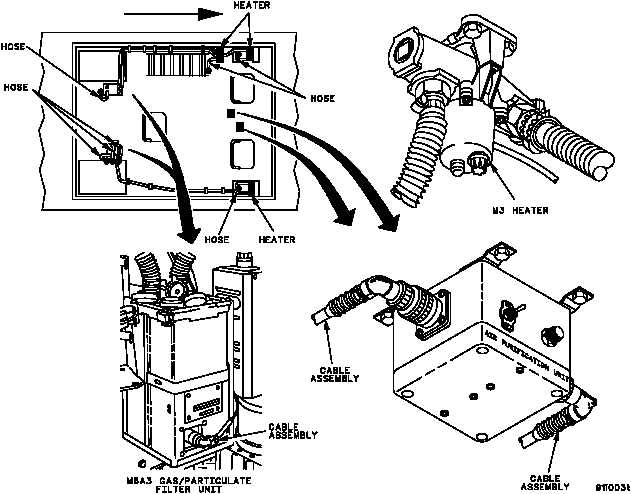
Also contained within the gas/particulate system are three M3 heaters. The M3 heaters are used to heat the air
supplied to the commander’s station, driver’s station and mechanic’s station when necessary. The M3 heaters are
controlled by the gas/paritculate filter system control unit and will only operate when the system is turned on.
The relationship of the gas/particulate filter unit system components is shown in the following illustration.
FORWARD
END OF TASK
0077 00--1/2 blank