TM 9--2350--292--20--1
0108 00--2
LIGHTS OVERVIEW AND DIAGRAMS -- CONTINUED
0108 00
When the main light switch is set to any position except OFF, the rear service lights are turned on by setting the
REAR SERVICE light switch to the ON position.
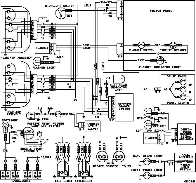
The warning flasher operates independently of the other external lights. A separate system power (+24 -- 28 V dc)
input is supplied to the FLASHER switch through a 15--amp circuit breaker on the switch panel. When the FLASH-
ER switch is set to the ON position, the flasher control is activated and the warning light flashes. Additionally, the
flasher indicator light flashes whenever the warning flasher light is operating.
A diagram is included to show the relationship of the various lighting components.
END OF TASK