TM 9--2350--292--20--1
0005 00--13
THEORY OF OPERATION -- CONTINUED
0005 00
AUXILIARY POWER UNIT (APU) -- CONTINUED
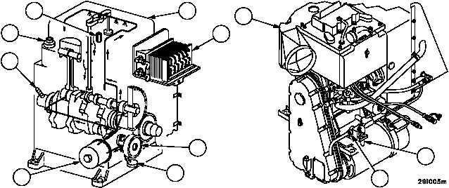
The APU lubrication system includes a gear--type oil pump assembly (4) with oil intake cup (5), a bypass valve (6),
an oil cooler (7) and an oil filter (8). Oil lines and passages distribute oil to the working parts of the auxiliary power
unit (1). A crankcase breather (9) is used to aid oil consumption control. The standpipe breather (10) vents crank-
case fumes from the rocker arm cover (11) to the cylinder head intake port. Normal oil pressure should be 16 to 25
psi (110.2 to 172.2 kPa) under normal operating conditions. A crankcase oil drain valve (12) with operating handle
(13) is provided to drain the lubricating oil without removing the unit from the vehicle.
1
13
12
4
8
7
11
9
6
10
5
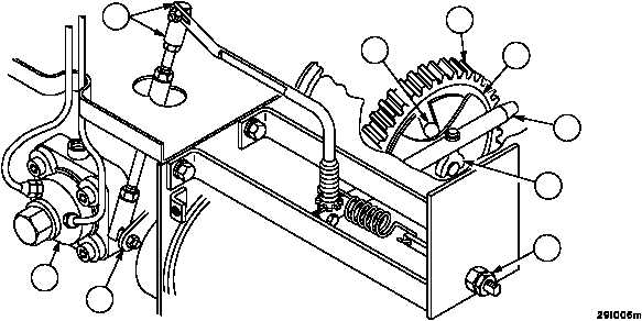
A constant speed governor is set to maintain engine speed at 2400 + 50 rpm at rated load. The governor uses a
flyball (14) and cup mechanism (15) on the camshaft gear (16) as the sensing device. Any change in engine speed
is transmitted from the yoke (17), through the governor shaft (18), arm and linkage (19) to the control lever (20) on
the injection pump (21). The speed may be adjusted by changing the spring tension, using the speed adjusting nut
(22).
16
19
14
15
17
18
22
20
21


