TM 9--2350--292--20--1
0005 00--18
THEORY OF OPERATION -- CONTINUED
0005 00
DEEP WATER FORDING KIT -- CONTINUED
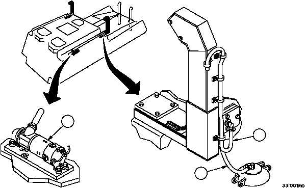
Acetylene Compartment Vent
A vent assembly (3) consisting of tubing, fittings, adapter plate and gasket is at-
tached to a boss which surrounds four vent holes in the left rear of the cab, to provide ventilation of the compart-
ment during the deep water fording operations. Two clips mounted on the left main engine air intake pipe support
the vent system.
Fuel Tank Vent The fuel tank vent (4) consists of two 90--degree elbows, a rubber hose, two hose clamps, a seal
and a clip. The rubber hose is clamped to an elbow in the left main engine air intake pipe and to an elbow in the
fuel tank’s filler cover. The seal is installed between the bottom of fuel tank filler cover and the top of the fuel tank
filler cap to prevent entry of water. The clip, attached to the acetylene vent cover, keeps the hose from hanging free
and being torn.
Bilge Pump, Motor and Support Assembly A centrifugal--type bilge pump (5) with motor and support assembly
is installed on the hull floor in the winch compartment. The pump (5) is used to remove any water which may enter
the compartment during fording. The discharge of the pump (5) is directed through the bilge pump hose to an outlet
adapter, mounted onto the right side of the personnel compartment. A toggle switch and indicator lamp for operat-
ing the pump (5) are located at the right of the driver’s seat on the accessories panel. A relay, which is activated by
the toggle switch, controls the pump motor. A circuit breaker and relay mounted under the floor plates provide over-
load protection for the pump circuit. The switch and relay coil circuit is protected by a circuit breaker on the acces-
sories panel.
3
4
5


