TM 9--2350--292--20--1
0005 00--16
THEORY OF OPERATION -- CONTINUED
0005 00
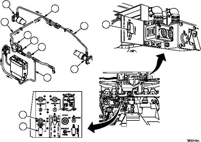
EXHAUST SMOKE GENERATING SYSTEM
The exhaust smoke generating system consists of a solenoid valve (1), two switch assemblies (2), a manual shutoff
valve (3), an indicator light (4), fuel tube assemblies (5), mounting brackets, electrical leads and attaching hard-
ware.
The solenoid valve (1) and fuel tube assemblies (5) are attached to the rear of the engine. Fuel to operate the
smoke generating system is taken from the main fuel supply at the front of the engine.
The switch (2) to operate the smoke generating system is installed in the driver’s compartment and commander’s
station and is connected to the main wiring harness using electrical leads provided in the smoke generating system
kits.
The smoke generating system uses the engine fuel pump to supply fuel from the vehicle fuel tanks to a solenoid
valve (1) mounted at the rear of the engine. When the solenoid valve (1) is energized (opened) it allows fuel to be
sprayed into the exhaust system (6). The fuel vaporizes and exits with the engine exhaust gases. The fuel vapor
cools on contact with the moving exhaust air and condenses to form a dense smoke screen. The electrical power
to energize the solenoid valve (1) is supplied by the warning indicator and warning horn systems. The warning horn
will not sound unless the engine is running. Connection to this system prevents accidental activation of the smoke
generating system when the engine is not running.
The manual fuel shutoff valve (3) can be used to determine if the smoke produced is from a malfunctioning engine
or from the smoke generating system.
2
4
2
5
5
3
1
5
6
5
5
6