TM 9--2350--292--20--1
MASTER RELAY AND SLAVE RECEPTACLE OVERVIEW AND DIAGRAMS.
0125 00
THIS WORK PACKAGE COVERS:
Master Relay And Slave Receptacle Overview and Diagrams
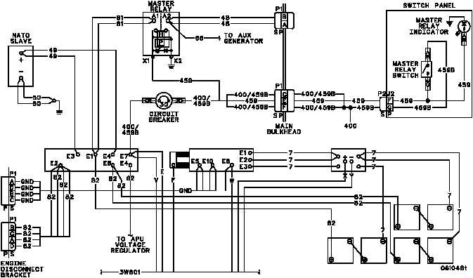
The master relay and slave receptacle system consists of the positive bus, negative bus, batteries, shunts, the
master relay, a MASTER switch, a MASTER relay indicator light, a 30--amp circuit breaker, and related electrical
wiring. The master relay and slave receptacle system switches and distributes electrical power (+24 -- 28 V dc) to
most of the vehicle electrical components. The source of electrical power can be either the batteries (+24 V dc),
main engine generator (+28 V dc), APU engine generator (+28 V dc), or an external source (+24 -- 28 V dc). Not
all electrical components are supplied system power from the master relay. Some circuits, such as the personnel
heater, operate directly from battery or generator power outputs while others in the exhaust smoke generator, main
engine monitoring system, engine accessories and warning system operate only from output power produced by
the main engine generator. The 30--amp circuit breaker provides overload protection for the master relay and per-
sonnel heater circuits
When the MASTER switch is turned ON, battery power (+24 V dc) energizes the master relay to supply system
power to the vehicle electrical components including the main engine starting system. Additionally, the MASTER
indicator lights to show that system power is available in the vehicle. After the engine is started and running, the
generator power output (+28 V dc) is supplied as system power through the master relay and distributed through
the vehicle. Power can also be supplied by the auxiliary power unit or from an external source. When an external
source is used, power is supplied by way of the slave receptacle. The various vehicle power sources can also be
used as an alternate power source for other vehicles. In this case, power is supplied from the slave receptacle to
the other vehicle.
Since the MASTER switch controls the application of system power to most of the vehicle electrical components,
turning the MASTER switch OFF will shut down vehicle system power. The MASTER switch should be set to the
OFF position when starting maintenance procedures.
The relationship of the master relay and slave receptacle components is shown in the following diagram.
END OF TASK
0125 00--1/2 blank