TM 9--2350--292--20--2
0379 00--4
BRAKE POWER BOOST HYDRAULIC MANIFOLD REPAIR (NEW
CONFIGURATION) -- CONTINUED
0379 00
Installation
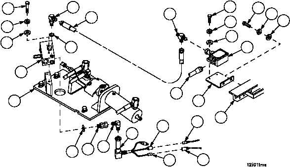
1. Apply a thin even coat of clean lubricant to all new preformed packings prior to installation.
2. Install power boost hydraulic manifold (11) on plate assembly (27) with two screws (24), two new lockwashers (25)
and two flat washers (26).
3. Install new preformed packing (23), adapter (22), adapter (21) and pressure switch (20) on power boost hydraulic
manifold (11).
4. Install pressure switch bracket (15) on support (19) with two screws (16), two new lockwashers (17) and two flat
washers (18).
5. Install pressure switch (2) on pressure switch bracket (15) with two screws (12), two new lockwashers (13) and
two flat washers (14).
6. Install elbow (8) with new preformed packing (10) in power boost hydraulic manifold (11) and tee (9) in pressure
switch (2).
7. Connect hose #444 (7) to tee (9) and elbow (8).
8. Connect wiring harness 2W601 wire 591 (5) to pressure switch lead (6).
9. Connect wiring harness 4W100 wire 48 (3) to pressure switch lead (4).
10. Connect wiring harness 4W100 connector P1 (1) to pressure switch (2).
3
4
5
6
2
1
11
27
24
25
26
8
10
7
9
12
13
14
16
17
18
15
23
22
21
20
19
NOTE
FOLLOW--ON MAINTENANCE:
Connect hydraulic hoses to brake power boost hydraulic
manifold (WP 0361 00)
Install subfloor plates #14 and #16 (WP 0454 00)
Connect battery power (WP 0256 00))
END OF TASK


