TM 5-4240-501-14&P
GOV. CONTROLS & CARB. LINKAGE
General
Fig. 4 illustrates typical remote control installations used
with Choke-A-Matic carburetors. To adjust, move remote
control lever to "FAST" position. Choke actuating lever
"A" should just contact choke shaft "B" or link "B" as
shown in Fig. 4. If not, loosen screw "C" slightly and
move casing and wire "D" in or out to obtain this
condition.
Fig. 4 - Choke-A-Matic Control (Typical)
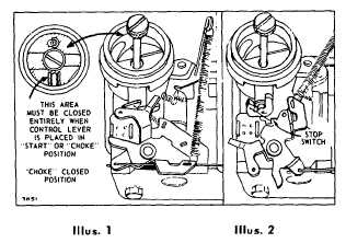
Check operation by moving remote control lever to
"START" or "CHOKE" position. Choke valve should be
completely closed. Fig. 5. Illus. 1. Then move remote
control lever to "STOP" position. Control must contact
stop switch blade. Fig. 5. Illus. 2.
Fig. 5 - Choke and Stop Position
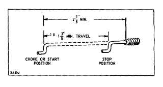
Travel of remote control wire must be a minimum of 1-
3/8" in order to achieve full "CHOKE" and "STOP"
position. Fig. 6.
Fig. 6 - Control Wire Travel
CHOKE-A-MATIC DIAL CONTROL
ADJUSTMENTS
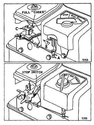
Dial Controls seldom require adjustment unless blower
housing has been removed. To Adjust: Place dial control
knob in "Start" position. Loosen control wire screw "A" -
move lever "C" to full choke position. Allow a 1/8" gap
between lever and bracket as shown.
Fig. 7 - Choke-A-Matic Dial Control Adjustments
2