TM 5-4240-501-14&P
CARBURETION
Fuel Pumps
Operation
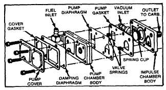
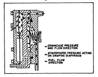
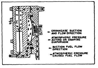
Operation of the fuel pump is illustrated in Figs. 119, 120
and 121. Any restriction in the fuel or vacuum lines will
affect operation. Also any leaks that cause air to get into
the fuel line or reduce vacuum in the vacuum line will
reduce performance.
Fig. 119
Fig. 120 - Fuel Flow with Crankcase Pressure
Fig. 121 - Fuel Flow Crankcase vacuum
To service fuel pump, pump should be removed from
carburetor or mounting bracket. When removing fuel
supply line from tank to pump, be sure to plug fuel line or
turn off fuel valve, if so equipped.
Disassemble fuel pump by removing four (4) 1/4" head
cap screws from pump cover. Separate pump cover,
pumping chamber and impulse chamber. Discard old
gaskets, diaphragms and springs. Clean pump parts in
carburetor solvent or lacquer thinner.
A repair kit is available. See Illustrated Parts Lists. The
kit includes all parts needed. Install chamber gasket
using locator pins. Place springs in spring recesses and
install pump diaphragm locator pins. Place pump
chamber body on impulse body using locator pins. Place
damping diaphragm and cover gasket on pump body.
Install cover and four (4) screws. Torque screws to 10-
15 in. lbs. (.12-.17 mkp, 1.13-1..69 Nm). See Fig. 119
for exploded view.
FUEL PUMPS,
ECCENTRIC OPERATED
To Replace Pump Diaphragm
Remove pump from cylinder and then remove four
screws to separate pump head from pump body.
With a narrow punch, drive lever pin out until pump lever
is loose. Pin may then be driven in either direction, but
need not be removed entirely. Remove old diaphragm,
but leave diaphragm spring in pump body.
Place new diaphragm into pump body with the slot in
shaft at right angles to the pump lever. Diaphragm spring
should fit into the cup under the diaphragm. Without the
lever spring, insert the pump lever into body holding the
diaphragm down. Fit the hook at the end of lever into the
slot in diaphragm shaft. Fig: 122.
Assemble Fuel Pump
Align holes in lever and body, then drive lever pin into
place. Place lever spring into body with inner end of
spring over the projection in pump body, then use a
screw driver to force outer end of spring into body until it
slips over the projection on lever. Fig. 122, Illus. 2.
Place pump head on body and partially insert the four
screws. Press pump lever down as far as possible and
then tighten the four screws.
34