TM 5-4240-501-14&P
CARBURETION
Kerosene and Fuel Pumps
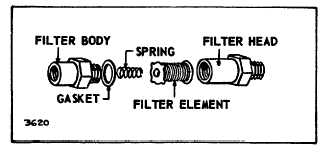
To re-assemble filter, insert element into filter head with
the round washer entering first. The gasket is put on the
filter body. The spring is located in the filter body so that
when filter body and head are put together, the spring will
hold the element against the head. Tighten body and
head with 75 foot lbs. (10.4 Kg/m, 8.5 N/m) of torque.
After filter has been re-assembled to engine, the point at
the gasket and other line connections should be checked
with soap suds, with fuel turned on, to be sure there are
no leaks.
Fig. 111 - Element Assembly
KEROSENE OPERATION
Efficient engine performance will be obtained only when
the following changes are accomplished:
1.
A low compression cylinder head is required for
models 23, 23A, 23C, 23D, 131400, 231000, 233000,
and 243000. Other models may use two cylinder head
gaskets.
2.
A special spark plug - #291835 - must be used on
models 23C, 23D, 233000, and 243000. Spark plug gap
.030" all models.
3.
A reduced breaker gap .015 is used on models
23C, 23D, 233000 and 243000. The engine must be
retimed using the reduced breaker gap. Follow timing
procedure in Ignition Section.
Power loss will vary between 15% to 25% and fuel
consumption will be approximately 15% less while
running on kerosene.
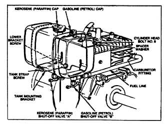
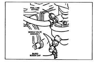
Fig. 112 through Fig. 115 illustrates various types of
Briggs & Stratton combination fuel systems used.
Due to the low volatility of kerosene, engines operated
on kerosene-gasoline fuel systems can be started on
kerosene
only
when
the
engine
is
at
operating
temperature. Cold engines must be started on gasoline,
and switched over to kerosene operation only after
warmed up.
After warm-up and while operating on kerosene, adjust
carburetor needle valves to a point where engine runs
smoothest, and accelerates without hesitation when
throttle is quickly opened. When shutting down engine,
the carburetor must be emptied of kerosene so the
engine can be started on gasoline when cold. Refer to
Flo-Jet Carburetor for adjustment of carburetor and
adjust carburetor while running on kerosene.
Fig. 112 - Combination Fuel Tank
Fig. 113A - Combination Fuel Tank
Fig. 113B - Combination Fuel Tank, Carburetor
32


