TM 5-4240-501-14&P
Fig. 122 - Fuel Pump
To Install Fuel Pump
Place a liberal supply of grease or gear lubricant on the
portion of fuel pump lever that contacts the crankshaft.
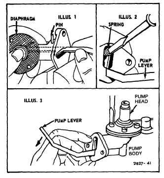
Fig. 123. Assemble fuel pump to cylinder using new
gasket. Keep mounting face of fuel pump parallel to
mounting face of cylinder while inserting lever of fuel
pump. The lever must ride in the narrow groove which is
located on the crankshaft between the gear and the
counter- weight. Revolve crankshaft to be sure that fuel
pump is correctly installed. Assemble fuel pipe from
outlet of carburetor. Fuel supply pipe should be
connected to the inlet of the fuel pump.
Fig. 123 -- Installing Fuel Pump
CARBURETION
Fuel Pumps, Automatic Chokes, Two Piece Flo-Jet
AUTOMATIC CHOKE
Automatic Choke Adjust
Hold choke shaft so thermostat lever is free. At room
temperature the screw in the thermostat collar should be
in the center of the stops, if not, loosen stop screw and
adjust.
Loosen set screw on lever of thermostat assembly.
Slide lever to right or left on shaft to insure free
movement of choke link in any position. Rotate
thermostat shaft clockwise until stop screw strikes tube.
Fig. 124. Hold in position and set lever on the thermostat
shaft so that choke valve will be held open about 1/8"
from closed position. Then tighten set screw in lever.
Rotate thermostat shaft counterclockwise until stop
screw strikes the opposite side of tube. Fig. 124. Then
open choke valve manually until it stops against the top
of the choke link opening. The choke valve should now
be open approximately 1/8" as before.
Fig. 124 - Adjust Automatic Choke
Check position of counterweight lever. With the choke
valve in wide open position (horizontal) the counterweight
lever should also be in a horizontal position with free end
toward the right.
Operate the choke manually to be sure that all parts are
free to move without binding or rubbing in any position.
35