TM 5-4240-501-14&P
CARBURETION
L. P. Fuel
Governed Idle
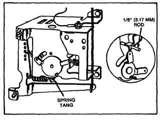
Turn idle speed adjusting screw to obtain 1600 R.P.M.
while holding throttle lever against screw. Release
throttle lever. Align holes in control bracket and inside
lever with 1/8" diameter rod. Governor speed control
lever of equipment should be in IDLE position. Adjust if
necessary. Bend spring tang to obtain 1750 R.P.M.
Remove 1/8" diameter rod, Fig. 109.
Fig. 109 - Governed Idle Adjustment
Needle Valve Mixture (High Speed)
Move governor speed control lever to "FAST" position.
Turn needle valve in until engine slows or misses (lean
mixture), then turn it out past the smooth operating point
until engine runs unevenly (rich mixture). Now turn
needle valve to the midpoint between rich and leans so
the engine runs smoothly, Fig. 108.
Engine should accelerate smoothly. If engine does not
accelerate properly, the carburetor should be re-adjusted
usually to a slightly richer mixture.
L. P. GAS FUEL SYSTEM
The following information is provided to assist you in
servicing LP gas fuel systems. This information applies
only to Garretson Equipment Company systems installed
by Briggs & Stratton. For parts information refer to MS-
3915. Parts for the Garretson system must be obtained
from
a
Garretson
parts
distributor.
For
information about LP conversion kits, contact:
Garretson Equipment Co., Inc.
Box 111
Mount Pleasant, Iowa 52641
or
Beam Products Manufacturing Co.
3040 Rosslyn Street
Los Angeles, California 90065
For LP fuel systems not covered in this section contact
the manufacturer of the fuel system.
WARNING: LP gas fuel system should only be worked
on in a very well ventilated area. Many state, county and
city governments require that service be performed only
outdoors. Before loosening any fuel line connections,
have a fan blowing directly across the engine.
Checking and Adjusting Fuel System
Loosen fuel line at primary regulator. Openvalve on
cylinder for an instant, to be sure there is pressure in fuel
cylinder. Escaping gas can be heard. Shut off valve at
cylinder, Fig. 110, page 32.
Remove fuel line between primary and secondary
regulator (fuel controller). Attach pressure gauge to
outlet of primary regulator, leaving gauge connection
loose enough to permit a slight leakage of gas. (This will
permit adjustment of regulator under conditions of actual
gas flow.) Remove cap or top of primary regulator, Fig.
110.
Open fuel cylinder valve. Turn pressure regulating screw
in primary regulator, until a pressure of 1-1/2 pounds is
obtained at pressure gauge. Shut off fuel cylinder valve.
Re-assemble cap. Remove pressure gauge. Loosen
secondary regulator bracket from carburetor. Pull
secondary regulator away from carburetor so that short
rubber fuel line is disconnected. Assemble fuel line
between primary regulator and secondary regulator (fuel
controller). Secondary regulator must remain mounted so
the diaphragm is in a vertical plane, Fig. 110.
Open fuel cylinder valve. Apply soap suds to outlet at
the center of secondary regulator to which rubber fuel
line has been attached. If a bubble forms, it indicates
that the valve is leaking or not locking off. If no bubble
appears, press the primer button. A bubble should
appear,
30