TM 5-4240-5501-148P
ALTERNATOR
11/2 Amp
NOTE: Ground wire or rectifier assembly must not touch
the engine during this test.
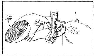
Start engine. With engine running, pierce stator wires
with probes from load lamp or touch terminals in rectifier
box. Fig. 154 and 155. If load lamp lights, the stator is
satisfactory. If load lamp does not light, the flywheel
magnet or stator is inoperative. The flywheel should be
examined to be sure magnet is charged. If required,
replace flywheel or the stator.
Fig. 154 Testing Stator
Fig. 155 Testing Stator (Alternator Style)
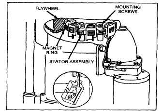
Replacing Defective Stator
Remove the blower housing, rotating screen, clutch
assembly and flywheel. Note and remember location of
stator wires, under one coil spool, then between starter
and drive unit housing as shown in Fig. 156. Remove
ground wire or rectifier assembly from starter drive
housing. Remove the two stator mounting screws and
bushings.
Fig. 156 Stator Assembly Location
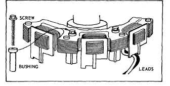
Install new stator assembly with stator mounting screws
and bushings. Be sure leads are properly positioned as
shown in Figure 157. While tightening mounting screws,
push stator toward crankshaft to take up clearance in
bushing. Torque mounting screws 18 to 24 inch pounds
(1.6 to 2.1 Nm). Before re-assembly, locate stator wires
against cylinder in order to clear ring gear and flywheel.
Attach ground wire or rectifier assembly to drive housing.
Replace flywheel and torque clutch housing as noted on
specification chart. Re-assemble rotating screen and
blower housing.
Fig. 157 Assembling Stator
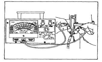
Testing Rectifier
Do not start engine. Use the #19236 VOA meter to test
resistance from charging terminal to ground, as shown in
Fig. 158 or 159. Now reverse test leads and recheck.
One way there should be a meter reading. The other
way there should not be a meter reading. The actual
meter readings are not important. If the meter shows a
reading both ways, or neither way, the rectifier is
defective. Replace rectifier.
49