ALTERNATOR
Dual Circuit - Fuse Type
Dual Circuit Alternator with Fuse
This efficient gear drive, 12 volt battery powered starter
system is compact and powerful. It is available with
either a rope or rewind auxiliary starter. Recommended
battery sizes range from 20 ampere hour for warm
temperature service to 40 ampere hour in coldest
service.
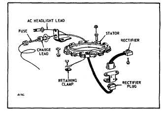
Fig. 175 - Alternator Assembly
DUAL CIRCUIT ALTERNATOR
The dual circuit alternator is actually two separate
alternator systems. A single ring of magnets inside the
flywheel supplies the mag-netic field for both of them.
One alternator system uses a solid state rectifier and
provides battery charging current. The other alternator
system feeds alternating current directly to the lights.
Since the two are electrically inde-pendent, use of the
lights does not reduce the charge going into the battery.
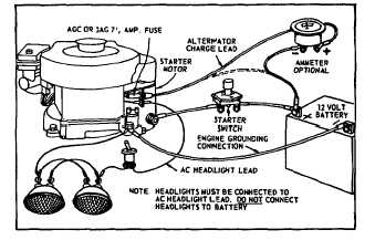
Fig. 176 - Typical Wiring Installation
The battery is not used for the lights, so lights are
available even if the battery is disconnected or removed.
Current for the lights is available as long as the engine is
running. The output depends upon engine speed.
Twelve-volt lights with a total rating of 60 to 100 watts
may be used. With lights rated at 70 watts, the voltage
rises from 8 volts at 2400 RPM to 12 volts at 3600 RPM,
so the brightness of the light changes with the engine
speed.
The current from the battery charging alternator is
unregulated and is rated at 3 amperes. The output rises
from 2 amperes at 2400 RPM to 3 amperes at 3600
RPM.
There are two external connections. The battery
charging current connection is made through a 7.5
ampere fuse mounted in a fuse holder beside the starter
motor. Current for the lights is available at a plastic
connector located below the fuse-holder. The two
connections are differ-ent so they cannot be accidentally
interchanged. The fuse protects the 3 amp charging
alternator and rectifier from burnout due to improper
(reverse polarity) battery connections. The 5 amp
lighting alternator does not require a fuse as a short
circuit in its output will not damage it. The return circuit
for both alternators is through ground to the engine
block. The alternator uses less than 0.2 horsepower.
CHECKING DUAL CIRCUIT ALTERNATOR
Fuse Blown
Check if battery polarity is correct: Negative (-) side of
battery should be grounded to engine or frame; positive
(+) side of battery to (fused) alternator output lead.
Figure 177. If reversed, correct and put in new fuse.
WHEN CHECKING ALTERNATOR COMPONENTS,
MAKE THE TESTS IN THE FOLLOWING SEQUENCE:
BATTERY RUNS DOWN
Testing Alternator Charging Output
Install ammeter in series with charging lead, as in Figure
177. Start engine. Ammeter should indicate charge.
The charge rate is dependent upon the condition of the
battery.
55


