ALTERNATOR
Dual Circuit- Fuse Type
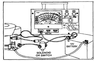
Fig. 177 - Testing Alternator Charging Output
If VOA meter shows no reading, test stator and rectifier.
Testing for Short in Stator or in Rectifier
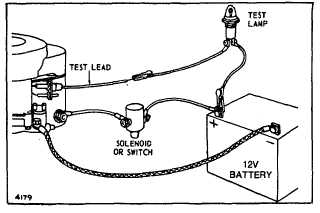
Disconnect charging lead from battery, and connect
small test lamp in series between battery positive
terminal and fuse cap, as shown in Figure 178. DO NOT
START ENGINE. Test lamp should not light. If it does
light, stator’s charging lead is grounded or rectifier is
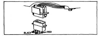
defective. Unplug rectifier plug under blower housing.
See Figure 179. If test light goes out, rectifier is
defective. If test light does not go out, stator charging
lead is grounded.
Fig. 178 - Testing for Short in Stator or Rectifier
Fig. 179 - Rectifier Plug
Testing Stator Charging Coils
If ‘”short” test indicates stator charging lead is grounded,
remove blower housing, flywheel, starter motor and
retaining clamp (see figure 175) and examine length of
red lead for damaged insulation or obvious shorts on
lead. If bare spots are found, repair with electrical tape
and shellac. If short cannot be repaired, replace stator.
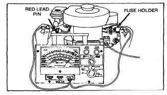
Charging lead should also be checked for continuity as
follows: Use multimeter, set on ohm Rx1 scale. Touch
one test prod to lead at fuse holder. Touch other test
prod to red lead pin in plastic connector: See Figure 180.
Unless the meter shows continuity, the charging lead is
open and the stator must be replaced.
Fig. 180 - Checking Charging Lead for Continuity
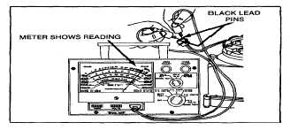
The charging coils should be checked for continuity as
follows: Using the multimeter, touch one test prod on
each of the black lead pins as shown in Figure 181.
Unless the meter shows continuity, charging coils are
defective and stator must be replaced. Test for
grounded charging coils by touching one test prod to a
clean “ground” surface on the engine and touching the
other test prod on each of the black lead pins as shown
in Figure 182. If the meter shows continuity, the
charging coils are grounded and stator must be replaced.
Fig. 181 - Checking Charging Coil Continuity
56

