ALTERNATOR
7 Amp
7 AMP REGULATED ALTERNATOR
Used on Model Series 140000, 170000 and 190000
The 7 ampere regulated alternator uses both a rectifier
and a solid state electronic regulator for rapid charging or
extra electrical loads. The regulator protects the battery
from overcharge. The alternator requires less than 0.2
horsepower.
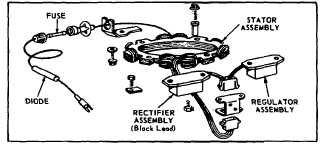
Fig. 186 - Alternator Assembly
Condition Found (Fuse Blown)
Check if battery polarity is correct. Negative (-) side of
battery should be grounded to engine or frame; positive
(+) side of battery to alternator output lead.
If reversed. correct and out in new fuse.
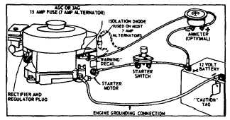
Fig. 187 - Typical Wiring Installation
Condition Found (Battery Run Down) Certain operating
conditions could cause the regulator to malfunction,
permitting the battery to discharge even after then engine
is stopped. To prevent such a malfunction, and the
possible inconvenience of a “dead” battery, an isolation
diode assembly (an electronic check-valve) is installed in
the alternator output lead, on engines with 7 ampere
regulated alternators.
The isolation diode assembly is installed at the time of
production, or may be added with kit #390607 described
as follows:
Disconnect cable from (-) negative (ground) battery
terminal. Unscrew fuse holder cap from fuse holder by
pushing in and twisting counter-clockwise. Remove and
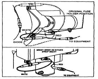
save fuse. Mount diode assembly in one of the various
positions shown in Fig. 188. Use ½” long screw,
lockwasher and flat washer. If diode assembly is
mounted on tank strap, install clamp between lock
washer and strap.
Fig. 188 - Diode Mounting Positions
The body of the isolation diode assembly should not rub
against any metal part. Repeated contact with a metal
part could wear through the insulation, causing a short.
Insert fuse in fuse holder on engine. Assemble fuse
holder cap on white lead of diode assembly to fuse
holder on engine. Attach connector on red lead of diode
assembly to original fuse cap, which was disconnected
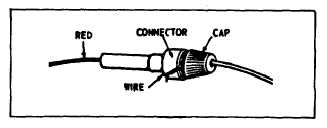
above. No fuse is used at this connection. Wrap two
turns of wire, provided with diode assembly, between cap
and socket. Secure the wires and socket with tape to
prevent rubbing or interference with other parts. See Fig.
189.
Fig. 189 - Wiring Connector
58