ALTERNATOR
7 Amp
Reconnect (-) negative (grounded) cable to battery post.
If necessary, recharge battery with a battery charger, or
by running engine 3 to 5 hours.
NOTE: An isolation diode is not required if the equipment
manufacturer routes the alternator output lead through a
special ignition switch, which disconnects the alternator
when the switch is in the “OFF” position.
WHEN CHECKING ALTERNATOR COMPONENTS,
MAKE THE TESTS IN THE FOLLOWING SEQUENCE:
Testing Isolation Diode
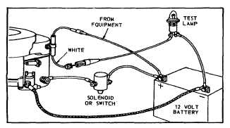
Unplug cap from fuseholder and connect small test lamp
between tip of white wire and battery negative terminal,
as shown in Figure 190. Lamp should not light. If lamp
lights, isolation diode is defective. Now disconnect test
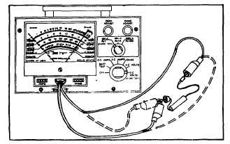
lamp, and check continuity from the tip of white diode
lead to tip of red diode lead with multimeter. The meter
should show continuity in one direction and not in the
other - reverse leads to check this, as shown in Figure
191. If indication is incorrect, diode is defective and
must be replaced.
Fig. 190 - Testing Isolation Diode System
Fig. 191 - Testing Isolation Diode
Testing for Shorts or Ground in Stator, Regulator or
Rectifier
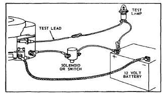
Disconnect charging lead from battery, and connect
small test lamp in series between battery positive
terminal and fuse cap, as shown in Figure 192. (Test
lead must not include an isolation diode.) DO NOT
START ENGINE. Test lamp should not light. If it does
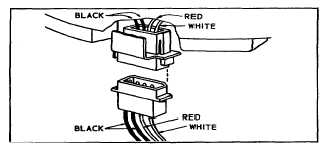
light, stator or regulator or rectifier is defective. Unplug
rectifier-regulator plug under blower housing. See Figure
193. If test light goes out. rectifier or regulator is
shorted. If test light does not go out, stator is grounded.
Fig. 192 - Testing for Shorts
Fig. 193 - Regulator Rectifier Plug
Testing Stator
If test indicates stator is grounded, look for
obvious defects on leads. If bare leads are found, repair
with friction tape and shellac. If shorted leads are not
visible, replace stator. Stator should also be checked for
continuity as follows: Use multimeter, set on resistance
scale. Touch one test prod to lead at fuse holder. Touch
other test prod to each of the four pins in plastic
connector. Unless the meter shows continuity at each of
the four pins, the stator winding is open and the stator
must be replaced. Figure 194.
59