PISTONS - RINGS - RODS
Checking
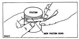
To do so, clean carbon from top ring groove. Place a
NEW ring on the groove, check the remaining space in
the groove with a feeler gauge. Fig. 5. If a .007" (0.18
mm) feeler gauge can be inserted (all models), the
piston is worn and should be replaced.
Fig. 5. Checking Ring Grooves
Check Rings
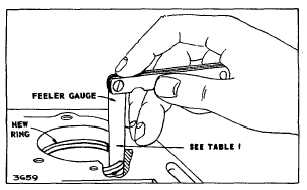
To check rings, first clean all carbon from the ends of the
rings and from the cylinder bore. Insert old rings one at
a time one inch down into the cylinder. Check gap with
feeler gauge. Fig. 6. If ring gap is greater than shown in
Table No. 1, the ring should be rejected.
Fig. 6. Checking Ring Gap
NOTE: Do not deglaze cylinder walls when installing
piston rings in aluminum cylinder engines.
Chrome Rings
NOTE: Chrome ring sets are available for all current
aluminum and cast iron cylinder models, no honing or
deglazing is required. The cylinder bore can be a
maximum of .005" (0.13 mm) oversize when using
chrome rings. See Service Bulletin 479 or Engine Parts
List.
TABLE NO. 1
RING GAP REJECTION SIZE
BASIC MODEL SERIES
COMP.
RING
OIL
RING
ALUMINUM CYLINDER
Inc
h
Mm
Inc
h
Mm
6B, 60000, 8B, 80000
82000, 92000, 110000, 111000
.035
0.80
.045
1.14
100000, 130000
140000, 170000, 190000, 250000
CAST IRON CYLINDER
Inc
h
Mm
Inc
h
Mm
5, 6, 8, N, 9
14, 19, 190000
200000, 23
.030
0.75
.035
0.90
230000, 240000
300000, 320000
TABLE NO. 2
CONNECTING ROD REJECT SIZES
BASIC MODEL SERIES
CRANK PIN
BEARING
PISTON PIN
BEARING
ALUMINUM CYLINDER
Inch
Mm
Inch
Mm
6B, 60000
.876
22.25
.492
12.50
8B, 80000
1.001
25.43
.492
12.50
82000, 92000, 110000
1.001
25.43
.492
12.50
100000
1.001
25.43
.555
14.10
130000
1.001
25.43
.492
12.50
140000, 170000
1.095
27.81
.674
17.12
190000
1.127
28.63
.674
17.12
220000, 250000
1.252
31.80
.802
20.37
CAST IRON CYLINDER
Inch
Mm
Inch
Mm
5
.752
19.10
.492
12.50
6, 8, N
.751
19.08
.492
12.50
9
.876
22.25
.563
14.30
14, 19, 190000
1.001
25.43
.674
17.12
200000
1.127
28.63
.674
17.12
23, 230000
1.189
30.20
.736
18.69
240000
1.314
33.38
.674
17.12
300000, 320000
1.314
33.38
.802
20.37
Check Connecting Rod
If the crankpin bearing in the rod is scored, the rod must
be replaced. Rejection sizes of crankpin bearing hole
and piston pin bearing hole are shown in Table No. 2.
Pistons pins .005" (0.13 mm) oversize are available in
case the connecting rod and piston are worn at the
piston pin bearing. If, however, the crankpin bearing in
the connecting rod is worn, the rod should be replaced.
Do not attempt to "file" or "fit" the rod.
Check Piston Pin
If the piston pin is worn .0005" (.01 mm) out of round or
below the rejection sizes listed below, it should be
replaced. Table No. 3.
2


