PISTONS - RINGS - RODS
Assembly
TABLE NO. 3
PISTON PIN REJECTION SIZE
BASIC MODEL SERIES
PISTON PIN
PIN BORE
ALUMINUM CYLINDER
Inch
Mm
Inch
Mm
6B, 60000
.489
12.42
.491
12.47
8B, 80000
.489
12.42
.491
12.47
82000, 92000, 110000
.489
12.42
.491
12.47
100000
.552
14.02
.554
14.07
130000
.489
12.42
.491
12.47
140000, 170000, 190000
.671
17.04
.673
17.09
220000, 250000
.799
20.29
.801
20.35
CAST IRON CYLINDER
Inch
Mm
Inch
Mm
5, 6, 8, N
.489
12.42
.491
12.47
9
.561
14.25
.563
14.30
14, 19, 190000
.671
17.04
.673
17.09
200000
.671
17.04
.673
17.09
23, 230000
.734
8.64
.736
18.69
240000
.671
17.04
.673
17.09
300000, 320000
.799
20.29
.801
20.35
Assemble Piston and Connecting Rod
The piston pin is a push fit in both piston and connecting
rod. On models using a solid piston pin, one end is flat,
the other end is recessed. Other models use a hollow
pin.
Place a pin lock in the groove at one side of the piston.
From the opposite side of the piston, insert the piston
pin, flat end first with solid pin, either end with hollow
pins, until it stops against the pin lock. Fig. 3. Use a thin
nose pliers to assemble the pin lock in the recessed end
of the piston. Be sure the locks are firmly set in the
grooves.
Assemble Rings to Piston
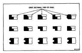
In Fig. 7, are shown the various rings and the proper
position of each. Note especially the center compression
ring. The scraper groove should always be down toward
the piston skirt. Be sure the oil return holes are clean
and carbon is removed from all grooves. NOTE: Install
expander under oil ring, when required.
Fig. 7. Position of Rings
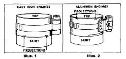
Oil the rings and piston skirt, then compress rings with
ring compressor (part 19070 or 19230). On all cast iron
models, use ring compressor (19070) as illustrated in
Fig. 8. Illustration 1. On all aluminum engines, use
compressor (19070) as illustrated in Fig. 8. Illustration 2.
NOTE: When using 19230 (2 band) ring compressor,
use as shown in Fig. 8, Illus. 1 on all engines.
Fig. 8. Compression Rings
Turn the piston and compressor upside down on the
bench and push downward, so the piston head and edge
of compressor band are even while tightening the
compressor. Draw the compressor up tight to fully
compress the rings, then loosen the compressor very
slightly. Do not attempt to install piston and ring
assembly without ring compressor.
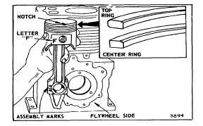
NOTE: The pistons used in the 220000 and 250000
engines have a notch as shown in Fig. 9. The notch
must face the flywheel side of the cylinder when
installed.
Installing Piston and Connecting Rod Models 300000
and 320000
The piston has an identification mark "F" located next to
piston pin bore. When assembling piston to the
connecting rod, the letter "F" on the piston must appear
on the same side as the assembly mark on the
connecting rod. Assembly mark on rod is also used to
identify rod and cap alignment. Install piston rings as
illustrated in Fig. 9.
Fig. 9. Assemble Piston to Rod
3