TM 5-4240-501-14&P
CRANKSHAFTS & CAM GEARS
Removal
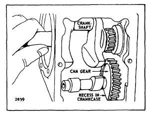
Fig. 4. Remove or Install Crankshaft
Model Series 9, 14, 19, 23, 200000, 230000
Plain Bearings
Remove crankshaft cover. Rotate crankshaft to
approximate position shown in Fig. 2. Pull out crankshaft
from P.T.O. side, twisting slightly, if necessary, to clear
cam gear.
Model Series 9, 14, 19, 23, 190000, 200000, 230000,
240000, 300000, 320000 Ball Bearings
NOTE: On 240000, 300000, 320000, piston and rod
must be removed from engine.
Remove crankcase cover and bearing support. Rotate
crankshaft to position shown, Fig. 2. On some models, it
may be necessary to position crankshaft approximately
180 from position shown in Fig. 2. Pull crankshaft out,
turning as needed to remove crankshaft.
To remove cam gear from all cast iron models, except
the 300000 and 320000, use a long punch to drive the
cam gear shaft out toward the magneto side. (Save
plug.) Fig. 3. Do not burr or peen end of shaft while
driving out. Hold cam gear while removing punch so
gear does not drop and nick.
Model Series 300400, 320400
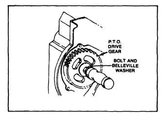
Remove short bolt and Belleville washer from P.T.O.
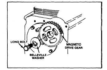
drive gear, Fig. 5. Loosen long bolt and Belleville washer
two (2) turns on magneto side and tap head of bolt with
hammer to loosen cam gear shaft. Turn bolt out while
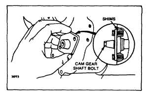
pushing out cam gear shaft. Remove bolts from cam
gear bearing, Fig. 6. While holding cam gear, remove
cam gear bearing and remove cam gear, Fig. 7.
Fig. 5. Remove Short Bolt
Fig. 6. Remove Long Bolt
Model Series 301400, 302400, 325400, 326400
Loosen long bolt two (2) turns. Use hammer to drive out
cam gear shaft and cam gear plug. Loosen bolt while
pushing out cam gear shaft and plug. Remove bolts and
cam gear bearing, Fig. 6. Remove cam gear, Fig. 7.
Fig. 7 - Removing Cam Gear Bearing
2