TM 5-4240-501-14P
IGNITION
MAGNETRONTM
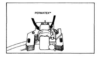
INSTALLING MAGNETRONT" MODULE
Module is installed in reverse order of removal. Note
that module retainer must be on back side of coil
laminations, Fig. 8. Use Permatex’" or similar sealant to
hold ground wires in place, Fig. 8
Ignition timing is controlled by the location of the flywheel
and crankshaft keyways on aluminum engines. On cast
iron engines, refer to page 9.
Fig. 8 -
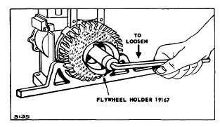
Starter Clutch On flywheels of 6-3/4" (171 mm) diameter
or less, use flywheel holder 19167, to keep flywheel from
turning. On rope starter engines, the 1/2" diameter
thread flywheel nut is left handed and the 5/8" diameter
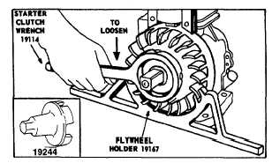
thread is right handed. Fig. 9. Starter clutch used on
rewind and wind-up starter has a right hand thread. Fig.
10. Remove clutch using P/N 19114 starter clutch
wrench or P/N 19244 or 19161 1/2" square drive starter
clutch wrench.
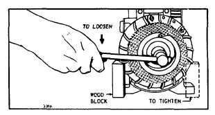
For flywheels or larger diameter place a block of wood
under flywheel fin to prevent flywheel turning while
loosening nut or starter clutch. Clamp engine base
securely. Fig. 11.
Fig. 9 Loosen Flywheel, Rope Starter (1/2" Dia.
Threads)
Figure. 10 - Loosening Flywheel
Rewind Starter and Wind-up Starter Engines
Fig. 11 - Loosening Large Flywheels
Remove Flywheel
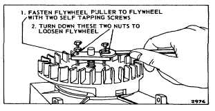
Some flywheels have two holes provided for use of a
flywheel puller. Use puller shown in Table 1. Leave nut
loose on threads of crankshaft for puller to bear against,
Fig. 12. Small cast iron flywheels do not require a
flywheel puller. See note below.
Fig. 12 - Removing Flywheel
NOTE : To remove small cast iron flywheels without
puller holes. support the flywheel with a gloved hand.
exerting an upward pull. Using a rawhide hammer.
strike the outside rim of the flywheel with a sharp blow.
Several blows may be required on an extremely tight
flywheel.
NOTE Care is required not to damage the flywheel fins.
magnets or ring gear
2
2
4