TM 5-4240-501-14P
IGNITION
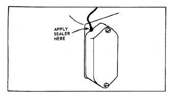
Flywheel Type - MAGNETRONTM - External Breaker
Fig. 28 - Sealing Breaker Cover
TIMING MAGNETRONTM IGNITION
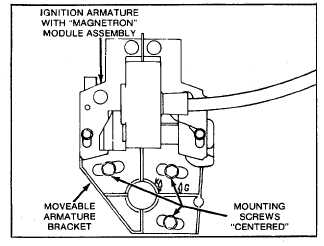
1
Gasoline
-
Position
armature
bracket
so
mounting screws are centered in armature
bracket and tighten screws, Fig. 29A.
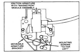
2.
Kerosene - Position armature bracket to the
right, as far as it will go and tighten screws, Fig.
29B.
Fig. 29A- Gasoline Operation
Fig. 29B- Kerosene Operation
ADJUST ARMATURE TIMING WITH
BREAKER POINTS
MODEL SERIES 193000, 200000, 230000 ,
243000, 300000, 320000
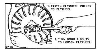
Remove Flywheel
Use puller 19203 or 19068, running puller screws into
holes tapped into flywheel. Continue to tighten screws
until flywheel loosens, Fig. 30. NOTE: Use flywheel nut
to protect crankshaft threads.
Fig. 30 - Removing Flywheel
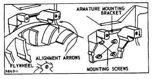
Set point gap at .020" (0.5 mm). Position flywheel on
crankshaft taper. Slip key in place. Install flywheel nut
finger tight. Rotate flywheel and crankshaft clockwise
until breaker points are just opening. Use a timing light.
When points just start to open, arrow on flywheel should
line up with arrow on armature bracket, Fig. 31.
If arrows do not match, slip off flywheel without disturbing
crankshaft position. Slightly loosen mounting screws
holding armature bracket to cylinder, Fig. 31. Slip
flywheel back on crankshaft. Insert flywheel key. Install
flywheel nut finger tight. Move armature and bracket
assembly to align arrows. Slip off flywheel, tighten
armature bracket bolts. Install key and flywheel. Tighten
flywheel nut to torque specifications listed in Table No.
1. Set armature air gap at .010"-.014" (0.25-0.36 mm),
Fig. 32.
Fig. 31 - Timing Marks
2
9