TM 5-4240-501-14P
IGNITION
Magna-Matic
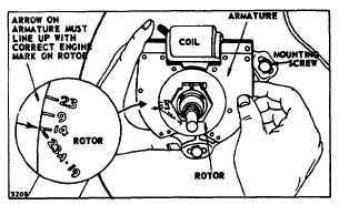
Fig. 50 - Adjusting Rotor Timing
Replace Coil or Armature or Both
Usually the coil and armature are not separated, but are
left assembled for convenience. However, if one or both
need replacement, proceed as follows: The coil primary
wire and the coil ground wire must be unfastened. Pry
out the clips that hold the coil and coil core to the
armature. See Fig. 51. The coil core is a slip fit in the
coil and can be pushed out of the coil.
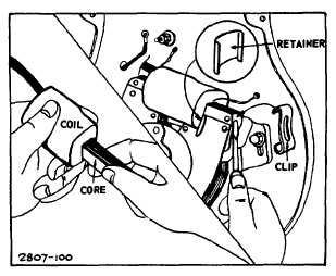
Fig. 51 - Replace Coil
To reassemble, push coil core into coil with rounded side
toward the ignition cable. Place coil and core on
armature with coil retainer between the coil and
armature, with rounded side toward the coil. Hook the
lower end of the clips into the armature; then press the
upper end onto the coil core, Fig. 51.
Fasten the coil ground wire (bare double wires) to the
armature support. (Replacing coil, Fig. 51). Now place
the assembly against the cylinder around the rotor and
bearing support. Insert the three mounting screws
together with washer and lockwasher into the three long
oval holes in the armature. Tighten them enough to hold
the armature in place but loose enough that the armature
can be moved for adjustment of rotor timing. See Fig.
50. Attach primary wires from coil and breaker points to
the terminal at the upper side of back plate. (This
terminal is insulated from back plate.) Push the ignition
cable through the louvered hole at left side of back plate.
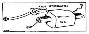
Fig. 52 - Shorten Cable - Model 9
NOTE: On Model 9 engines, knot the ignition cable
before inserting it through the back plate. See Fig. 52.
Be sure all wires clear flywheel.
Remove Breaker Points
Turn crankshaft until points open to widest gap. This
makes it easier to assemble and adjust points later if
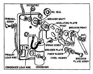
crankshaft is not removed. With terminal screw
removed, remove the spring screw. See Fig. 53.
Loosen the breaker shaft nut until nut is flush with end of
shaft. Tap nut to free breaker arm from tapered end of
breaker shaft. Remove nut, lockwasher and breaker
arm. Remove breaker plate screw, breaker plate, pivot,
insulating plate and eccentric. Pry out breaker shaft oil
seal with a sharp pointed tool.
Fig. 53 - Breaker Box Assembly
2
14