TM 5-4240-501-14P
IGNITION
Flywheel Type - External Breaker
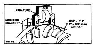
Fig. 32 - Armature Air Gap
ADJUST ARMATURE TIMING
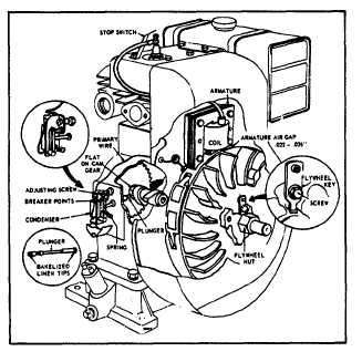
Model Series 19D, 23D
Fig. 33 - Model Series 19D, 23D
Remove Flywheel
Use puller 19203 or 19068, running puller screws into
holes tapped into flywheel. Continue to tighten screws
until flywheel loosens, Fig. 30.
NOTE : Use flywheel nut to protect crankshaft threads.
Set points at .020" (0.51 mm) gap. Position flywheel on
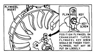
crankshaft taper. Flywheel key screw should be finger
tight. Flywheel nut may be put on loosely, Fig. 33.
Fig. 34 - Flywheel Key
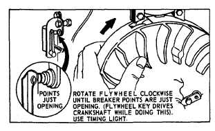
Rotate flywheel clockwise until breaker points are just
opening (flywheel key drives crankshaft while doing this).
Fig. 35. Use a timing light.
Fig. 35 - Flywheel Timing
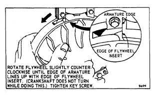
Rotate flywheel slightly, counterclockwise, until edge of
armature lines up with edge of flywheel insert, Fig. 36.
(Crankshaft must not turn while doing this.) Tighten key
screw. Tighten flywheel nut. See Table 1. Set armature
air gap at .022"-.026" (0.56-0.66 mm).
Fig. 36 - Flywheel Timing
2
10

